Eureka AIR delivers breakthrough ideas for toughest innovation challenges, trusted by R&D personnel around the world.

Collapsible decorative structure

a decorative structure and collapsible technology, applied in the field of decorative structures, can solve the problems of large storage space, large amount of setup time, and large amount of storage space, and achieve the effect of easy erecting and collapsing

Inactive Publication Date: 2008-01-22
QUIGEL CAMERON F
View PDF6 Cites 7 Cited by
  • Summary
  • Abstract
  • Description
  • Claims
  • Application Information

AI Technical Summary

Benefits of technology

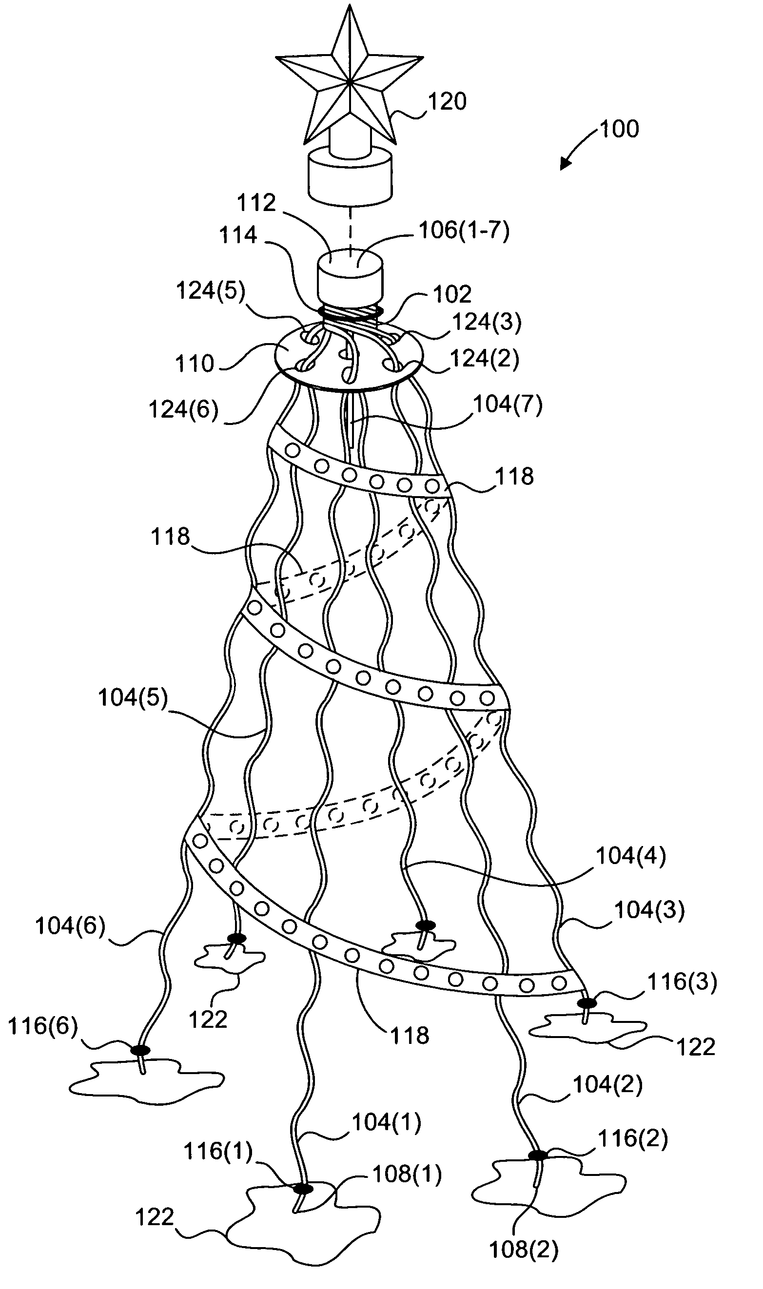
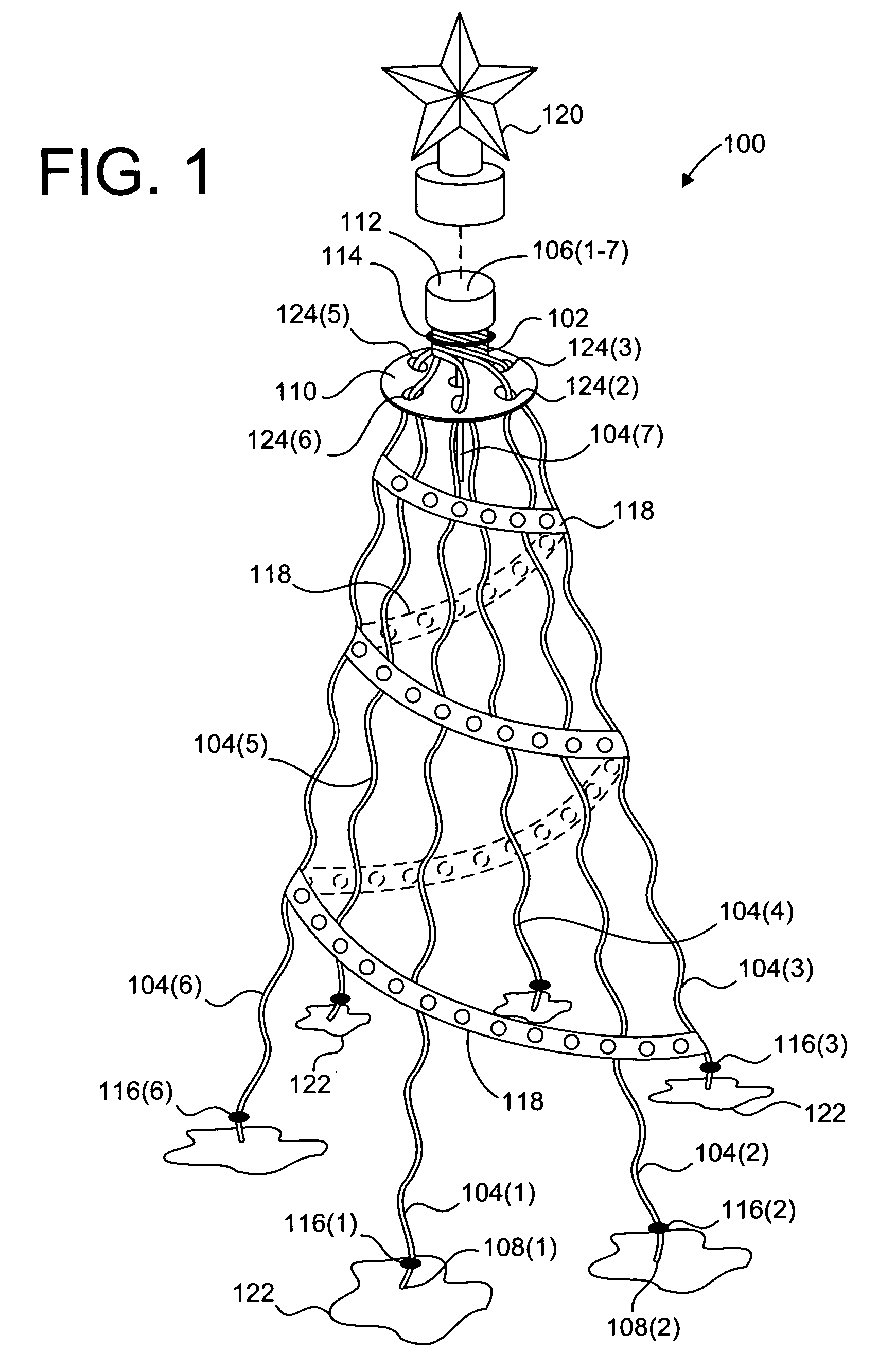
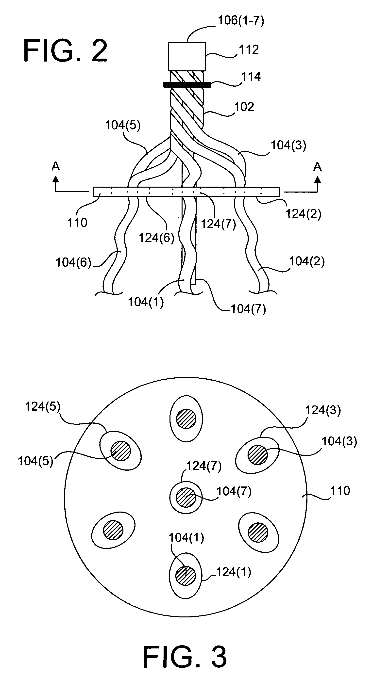
"The present invention provides a decorative structure that is easy to erect and collapse, and can support objects off the ground. The structure includes a length of strand material with twisted individual strands that are fixed together at one end, and a twisting member with a plurality of apertures for receiving the strands. The strands can be unwound from the second end to the first end using the twisting member, and the structure can be rewound by moving the twisting member in the opposite direction. The decorative structure is easy to open and close, and can be coated for protection and enhanced decorative appearance. The invention also provides a method for erecting the decorative structure."

Problems solved by technology

Indoor trees, for example, require large amounts of storage space because they are generally formed from many interconnecting components that have fragile branches and pine needles attached thereto for decoration.
Additionally, the components, because of their interconnecting complexities, require a substantial amount of time to setup.
Further, the wire frame structures are typically formed as a single unit, and therefore require a relatively large amount of storage space when not being displayed.
Like decorations, such support structures typically require disassembly and / or occupy significant storage space when not in use.

Method used


Image

  • Collapsible decorative structure
  • Collapsible decorative structure
  • Collapsible decorative structure

Examples


Embodiment Construction

[0037]The present invention overcomes the problems associated with the prior art, by providing a collapsible decorative structure (e.g., a Christmas tree) that is compact and easy to store, requires little assembly or disassembly, and has a structure that retains a decorative appearance when erected. In the following description, numerous specific details are set forth (e.g., number of individual strands in strand material, use of steel strand material, etc.) in order to provide a thorough understanding of the invention. Those skilled in the art will recognize, however, that the invention may be practiced apart from these specific details. In other instances, details of well known processes (e.g. strand material fabrication, powder coating, etc.) have been omitted, so as not to unnecessarily obscure the present invention.

[0038]FIG. 1 shows a decorative structure 100 according to one embodiment of the present invention. Decorative structure 100 includes a length of strand material 10...


PUM

PropertyMeasurementUnit
lengthaaaaaaaaaa
decorative structureaaaaaaaaaa
shapeaaaaaaaaaa

Abstract

A novel decorative structure includes a length of strand material, having a plurality of individual strands twisted with respect to one another and fixed with respect to one another near a first end of the strands, a twisting member having a plurality of apertures formed therein, each adapted to receive a respective one of the individual strands therethrough, and an anchoring member adapted to support the decorative structure on a support surface. In a particular embodiment the twisting member is a disc, such that when the twisting member is advanced from a second end of the strands to the first end, the strand material is caused to unwind. Similarly, when the twisting member is advanced from the first end to the second end of the strands, the strand material is caused to wind up. When unwound, the strands can support a container within the unwound ends of the strand material.

Description

RELATED APPLICATIONS[0001]This application is a continuation-in-part of prior U.S. patent application Ser. No. 10 / 251,250 filed on Sep. 20, 2002 by the same inventor, which issued Dec. 16, 2003 as U.S. Pat. No. 6,663,921, and which is incorporated herein by reference.BACKGROUND OF THE INVENTION[0002]1. Field of the Invention[0003]This invention relates generally to decorative and support structures, and more particularly to a collapsible Christmas tree and support structure that are easy to erect, easy to collapse, compact for storage, and whose structures have a decorative shape and can support additional items when erected, in either an upright or inverted position.[0004]2. Description of the Background Art[0005]During the holiday seasons, homes are commonly adorned in and out with festive decorations. One common decoration is the artificial Christmas tree.[0006]Artificial trees are designed and manufactured in both indoor and outdoor varieties. Indoor and outdoor type artificial ...

Claims


Application Information

Patent Timeline
Patent Type & Authority Patents(United States)
IPC IPC(8): A47G33/04A47G33/06B32B1/00F21W121/04
CPCA47G33/06
Inventor QUIGEL, CAMERON F.
Owner QUIGEL CAMERON F
Why Eureka
Eureka Blog
Learn More