
Data converting circuit, data converting method, and image forming apparatus

a data converting circuit and data technology, applied in the field of data converting circuits, data converting methods, image forming apparatuses, can solve the problems of reducing the actual memory capacity, increasing the cost and increasing the power consumption of the devices involved, and requiring a large memory capacity as a very heavy burden, so as to reduce the memory capacity

Inactive Publication Date: 2008-01-22
KK TOSHIBA +1
View PDF3 Cites 0 Cited by
  • Summary
  • Abstract
  • Description
  • Claims
  • Application Information

AI Technical Summary

Benefits of technology

[0006]The object of the present invention is to provide a data converting circuit to store an output signal corresponding to an input signal beforehand in a memory and subject the output signal to the converting process, a data converting circuit capable of greatly reducing a memory capacity and a data converting method and an image forming apparatus using the same.
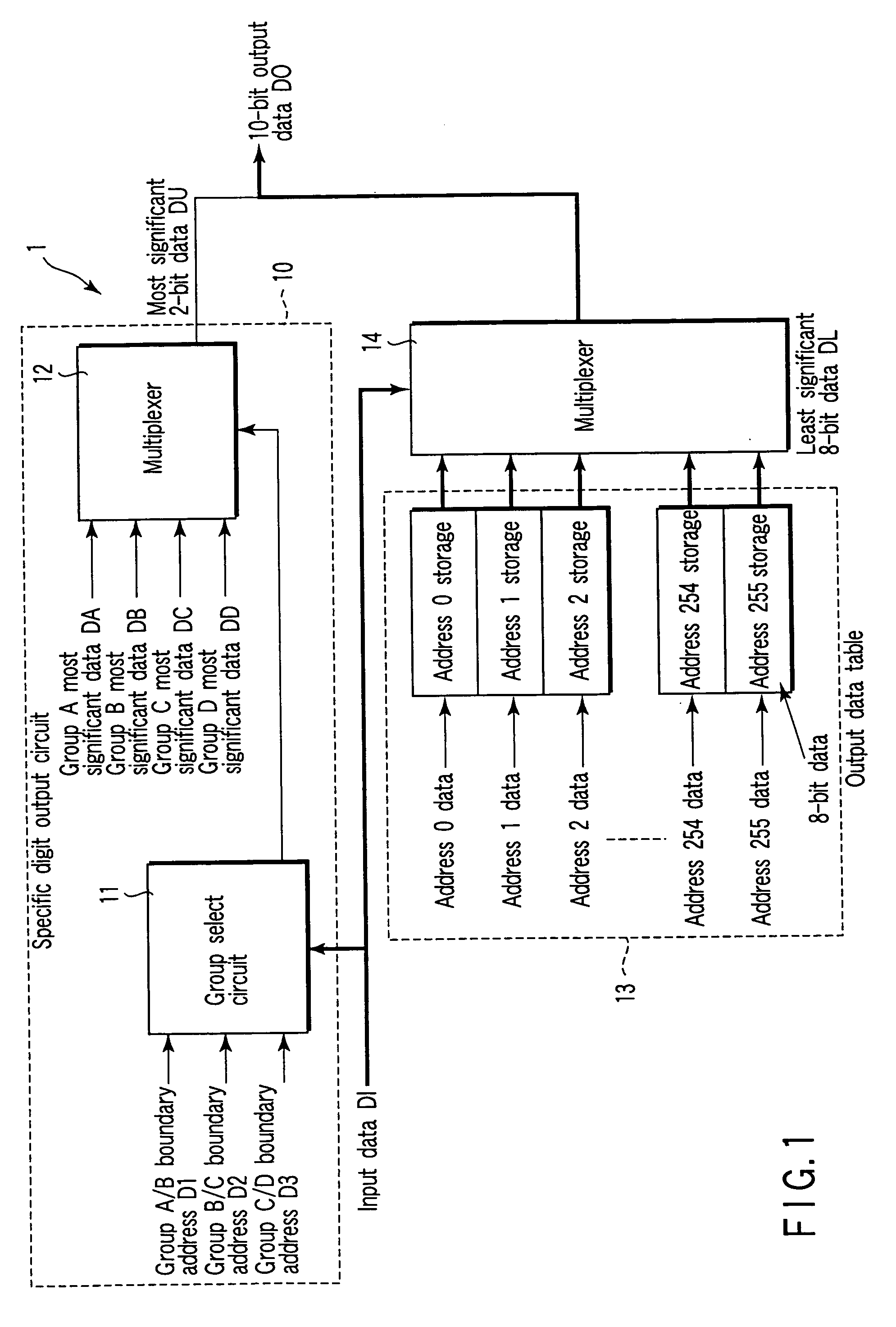
[0009]As a result, in the case where an 8-bit input data is converted into a 10-bit output data, for example, unlike in an apparatus to which the present invention is not applied, a memory having a storage capacity of 256×16 bits is not required to be secured. Specifically, an equivalent conversion function can be realized by a memory having a storage capacity of 256×8 bits and a specific digit output circuit including a memory having a storage capacity of several tens of bits and a comparator. In this case, therefore, the storage capacity of the memory required as a data converting circuit can be reduced to about one half, thereby providing a data converting circuit capable of saving the memory greatly.

Problems solved by technology

This data converting circuit is so basically structured that all the output signals corresponding to the input signals are prepared and stored in a memory in advance, and therefore a large memory capacity is required as a very heavy burden.
Nevertheless, the data converting process is not disclosed for a case in which the number of bits of the output signal is larger than the number of bits of the input signal, and no technique has yet to be disclosed to reduce the actual memory capacity.
This data converting circuit is often arranged in an ASIC or the like, and therefore an increased storage capacity of the RAM comes to pose the problem of a higher cost and an increased power consumption of the devices involved.

Method used


Image

  • Data converting circuit, data converting method, and image forming apparatus
  • Data converting circuit, data converting method, and image forming apparatus
  • Data converting circuit, data converting method, and image forming apparatus

Examples


Embodiment Construction

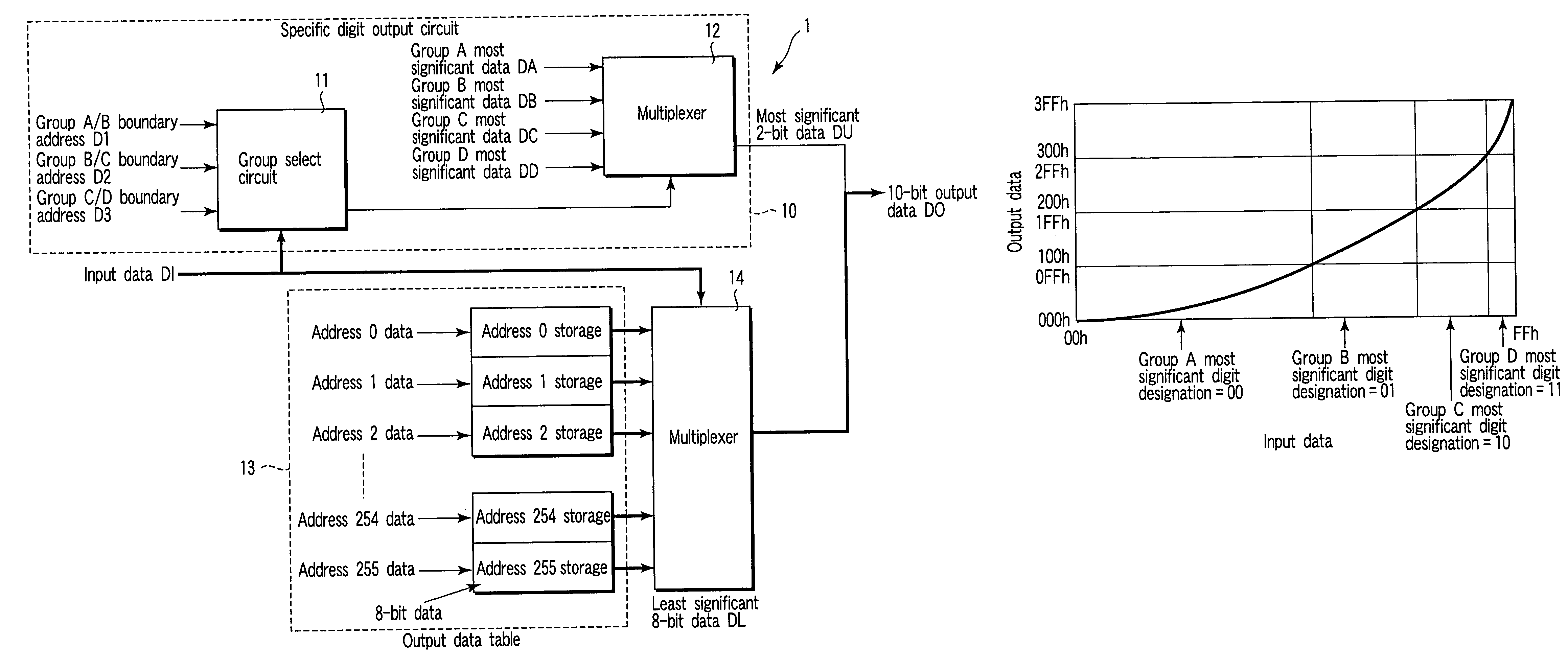
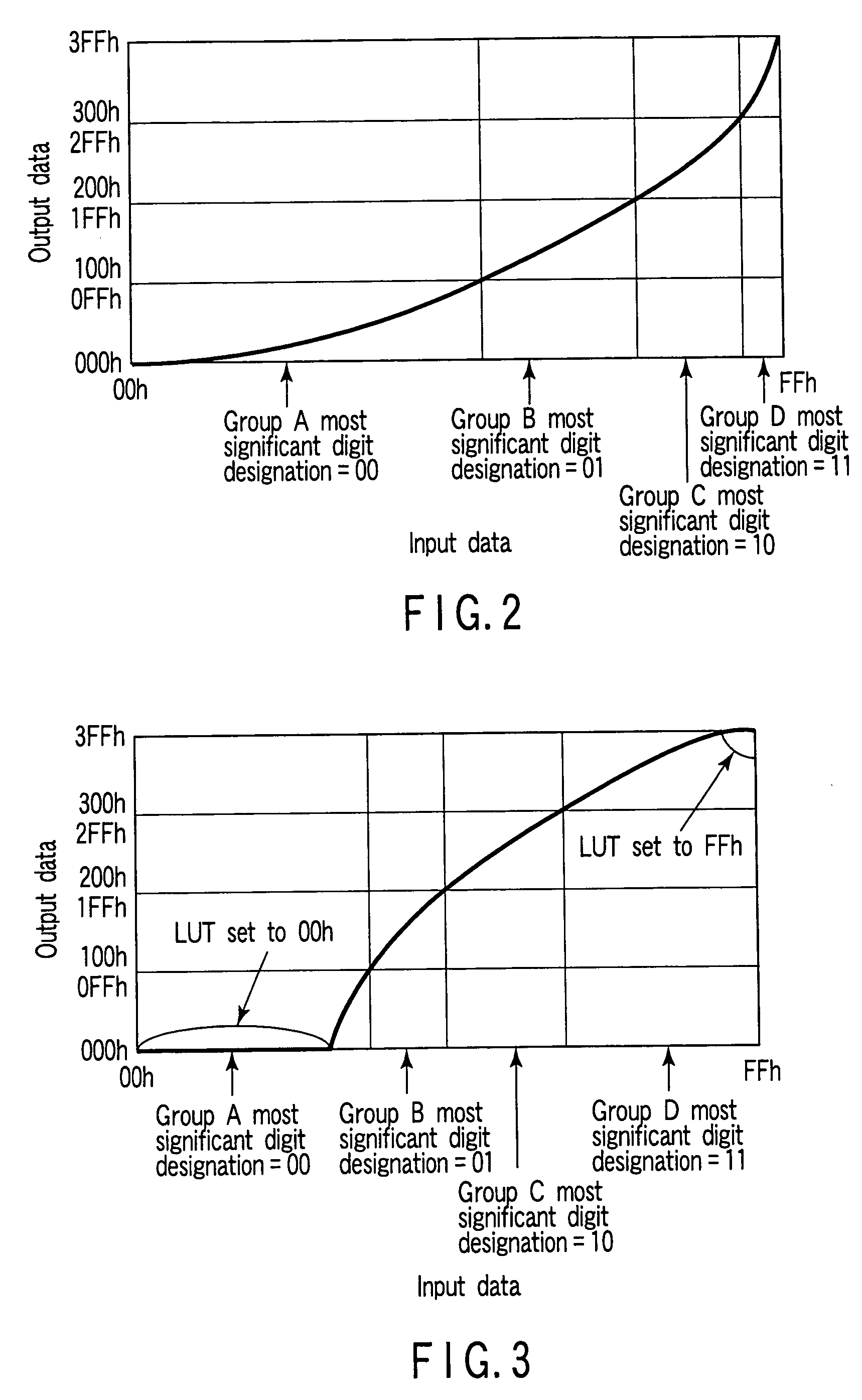
[0015]A data converting circuit, a data converting method and an image forming apparatus using the same according to the present invention will be explained in detail below referring to the accompanying drawings. FIG. 1 is a block diagram showing an example of a configuration of a data converting circuit according to the present invention, FIG. 2 a graph showing an example of the converting process of the data converting circuit according to the present invention, FIGS. 3 and 4 are graphs showing another example of the converting process, and FIG. 5 a block diagram showing an example of a configuration of an image forming apparatus using a data converting circuit according to the present invention.

Data Converting Circuit

[0016]A data converting circuit 1 according to the present invention comprises, as shown in FIG. 1, a specific digit output circuit 10 supplied with an input data DI from an external source, an output data table 13 similarly supplied with an input data DI, and a mult...


PUM


Abstract

A data converting circuit to receive an input data and convert the input data into an output data is disclosed. An output data group corresponding to the value of the input data is stored beforehand in an output data table. A multiplexer receives the input data and in accordance with the input data, selectively outputs one data out of the output data group stored in the output data table. A specific digit output circuit receives the input data and in accordance with the result of comparing the input data with the boundary information stored in advance, outputs a specific digit output data included in the output data but not output by the multiplexer.

Description

BACKGROUND OF THE INVENTION[0001]The present invention relates to a data converting circuit to receive an input signal constituted of a plurality of digital signals and subject the input signal to a predetermined data converting process and thereby output an output signal constituted of a plurality of digital signals, and an image forming apparatus using this data converting circuit as an image processing circuit.[0002]Currently, in an image processing circuit or the like of an image forming apparatus such as a digital duplicator, the data converting process is widely employed in which outputs corresponding to input data are prepared and stored in a storage unit as a group of output data, and by selectively outputting the output data from the storage unit, the data is converted so that an appropriate data after the data conversion is supplied to the circuits in subsequent stages. In the image correction of a duplicator, for example, the image data retrieved by a scanner unit is sent...

Claims


Application Information

Patent Timeline
IPC IPC(8): G06K15/00G06F13/00G06K13/28G06F1/03G06F3/00
CPCG06F1/0307
Inventor ONO, SHUNICHIKOBAYASHI, HIDENORI
Owner KK TOSHIBA
Learn More