Linearization of amplifiers using baseband detection and non-baseband pre-distortion

a technology of pre-distortion and linearization, applied in the field of signal processing, can solve the problems of increasing the cost, affecting the operation of the amplifier, and displaying non-linearity over the operating range of the amplifier, so as to improve the reliability and reliability of the amplifier. the effect of reducing the cos

Inactive Publication Date: 2008-01-22
COMMSCOPE TECH LLC
View PDF13 Cites 54 Cited by
  • Summary
  • Abstract
  • Description
  • Claims
  • Application Information

AI Technical Summary

Problems solved by technology

Amplifiers, such as high-power amplifiers used in the base stations of wireless communication systems, typically exhibit non-linearity over their operating ranges.
This non-linearity can result in noise that can corrupt or otherwise interfere with the communications.
Nevertheless, the RF pre-distortion implementation does involve more analog circuitry (in particular, delay 230 and ADC 233), which can increase the cost.
Moreover, performing envelope detection in the analog RF domain (using diode 232) can lead to accuracy problems relative to the detection in the digital baseband domain of the baseband pre-distortion implementation of FIG. 1.

Method used


Image

  • Linearization of amplifiers using baseband detection and non-baseband pre-distortion
  • Linearization of amplifiers using baseband detection and non-baseband pre-distortion
  • Linearization of amplifiers using baseband detection and non-baseband pre-distortion

Examples


Embodiment Construction

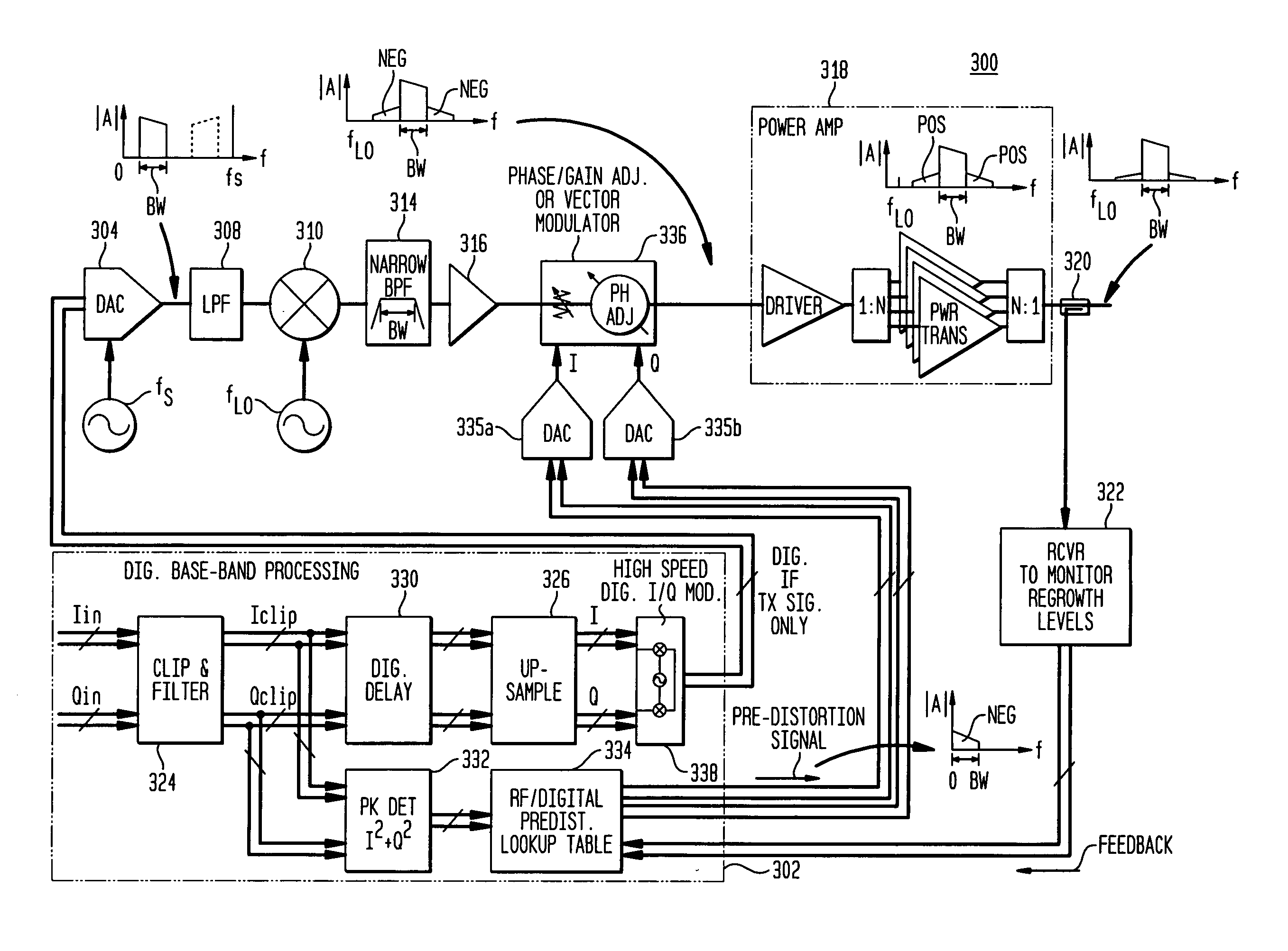
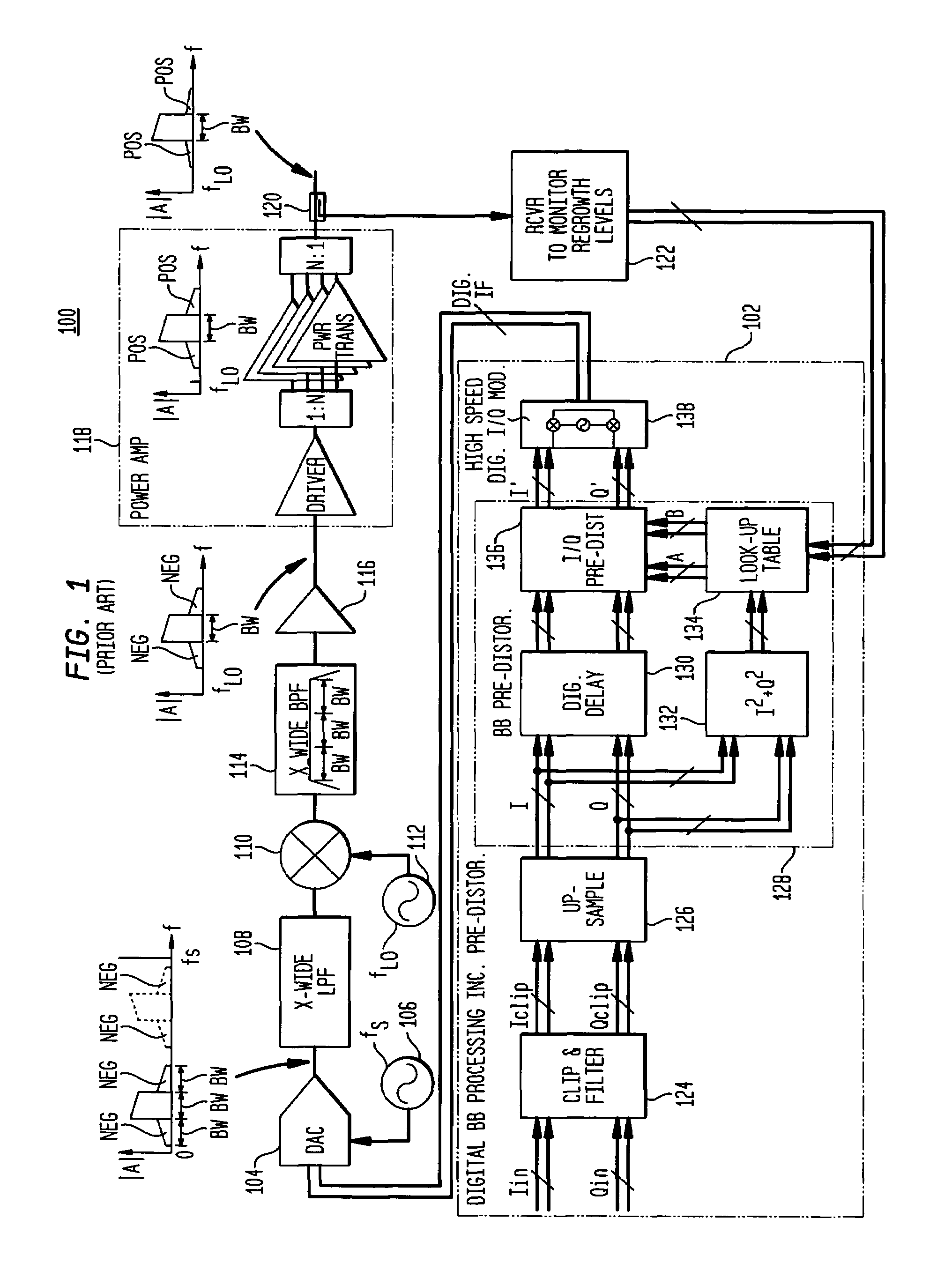
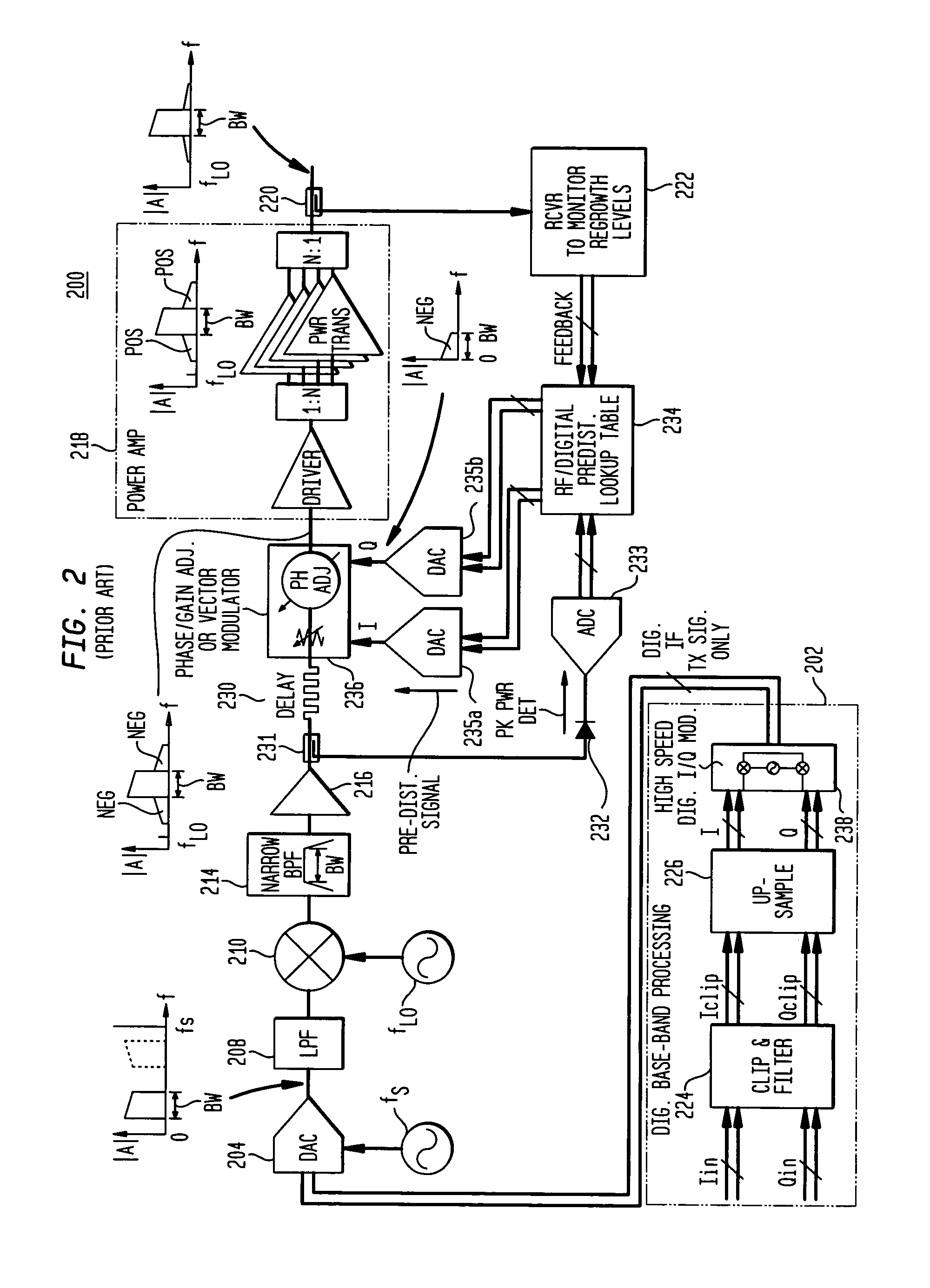
[0022]FIG. 3 shows a block diagram of a linearized amplifier system 300 according to one embodiment of the present invention. Unlike prior-art amplifier system 100, which performs its pre-distortion processing at baseband in the digital domain, and prior-art amplifier system 200, which performs its pre-distortion processing at RF, amplifier system 300 performs some of its pre-distortion processing at baseband in the digital domain and some of its pre-distortion processing at RF. In particular, digital baseband processor 302 functions as a digital baseband pre-distortion detector, which detects the signal envelope and retrieves the digital pre-distortion parameters A and B from a LUT at baseband, while the actual signal pre-distortion is performed by pre-distorter 336 (e.g., a phase / gain adjuster or a vector modulator) at RF in the analog domain.

[0023]In particular, processor 302 comprises clip & filter block 324, upsampler 326, and high-speed digital I / Q modulator 338, which are ana...


PUM


Abstract

In an amplifier system that linearizes an amplifier by pre-distorting the input signal prior to amplification, a baseband pre-distortion processor processes the input signal in a digital baseband domain to generate one or more pre-distortion parameters based on the power of the digital baseband input signal. The digital baseband signal is up-converted and D/A-converted into a non-baseband (e.g., IF or RF) signal which is then pre-distorted, e.g., using a phase/gain adjuster or a vector modulator. By generating the pre-distortion parameters at baseband, while pre-distorting the input signal at non-baseband, the amplifier system avoids the cost and inaccuracies associated with analog signal delay and RF power detection of prior-art “all-RF” pre-distortion implementations, while avoiding the wider-bandwidth filtering of prior-art “all-baseband” pre-distortion implementations.

Description

CROSS-REFERENCE TO RELATED APPLICATIONS[0001]This application claims the benefit of the filing date of U.S. provisional application No. 60 / 403,970, filed on Aug. 16, 2000.FIELD OF THE INVENTION[0002]The present invention relates to signal processing, and, in particular, to techniques for linearizing amplifiers based on pre-compensation.BACKGROUND OF THE INVENTION[0003]Amplifiers, such as high-power amplifiers used in the base stations of wireless communication systems, typically exhibit non-linearity over their operating ranges. This non-linearity can result in noise that can corrupt or otherwise interfere with the communications. To address this problem, additional circuitry may be added to an amplifier in an attempt to linearize the effective amplifier response. Conventional techniques for linearizing amplifiers typically involve feed-forward compensation and / or pre-compensation.[0004]In feed-forward compensation, an auxiliary signal is fed forward and combined with the output of ...

Claims


Application Information

Patent Timeline
Patent Type & Authority Patents(United States)
IPC IPC(8): H04K1/02H04L27/36
CPCH04L27/368
Inventor OCENASEK, JOSEFRUCKI, JOHN S.
Owner COMMSCOPE TECH LLC
Why Eureka
Try Eureka