High accuracy low leakage valve for high pressure applications

a high-precision, valve technology, applied in the direction of fluid pressure control, process and machine control, instruments, etc., can solve the problems of metering system error, drip-tight shutoff of throttle valves, and leakage of fluid conveying control pressure against the valve body between the valve body and the valve sleeve, so as to achieve low leakage or drip-tight shutoff. the effect o

Active Publication Date: 2008-01-29
HONEYWELL INT INC
View PDF19 Cites 14 Cited by
  • Summary
  • Abstract
  • Description
  • Claims
  • Application Information

AI Technical Summary

Benefits of technology

[0008]These shortcomings and others are addressed by the present invention which, in a first aspect, comprises a valve assembly of a fluid metering system. According to another aspect, the present invention is directed to a fluid metering system using a valve assembly described herein. One embodiment of the present invention utilizes a valve assembly with a channel in the valve sleeve to port metered flow pressure to an annulus to reduce the servo side matched clearance leakage to near zero. In one implementation, the valve of the valve assembly has a single diameter. This single diameter valve approach opens up numerous options, particularly for the upper seal design, making it much easier to achieve low leakage or drip-tight shutoff.
[0010]An additional aspect of the invention comprises a gas turbine engine throttle valve assembly including a throttle valve having a first end and a second end and comprising a valve sleeve and a valve body slidably mounted in the valve sleeve. A supply flow path delivers a supply fuel flow against the first end of the throttle valve to shift it between a first position blocking the at least one opening in the sidewall and a second position exposing at least a portion of the at least one opening to the supply fuel flow. A control flow path delivers a control fluid against the second end of the throttle valve and into a space between the valve body and a circumferential end section of the valve sleeve when the valve body is in the second position. The valve also includes a passage allowing communication between the supply fuel flow and the space between the valve body and the valve sleeve circumferential end section when the valve body is in the second position and substantially preventing communication between the supply fuel flow and that space when the valve body is in the first position.
[0012]In another aspect, the invention comprises a method of controlling a gas turbine engine throttle valve outlet flow that involves providing a throttle valve comprising a valve sleeve and a single diameter valve body slidably mounted in the valve sleeve. The valve sleeve has a sidewall having a first end and a second end, a central circumferential section including at least one opening, a first circumferential section lying between the first end and the central circumferential section and a second circumferential section lying between the second end and the central circumferential section. A supply fuel under pressure is directed against the first end of the throttle valve and a control fluid under pressure is directed against the second end of the throttle valve and into a space between the valve body and the valve sleeve second circumferential section. Fluid flow through the at least one opening is prevented by shifting the valve body into a first position and fluid flow is allowed through a passageway connecting the first circumferential section to the second circumferential section when the valve body is in the second position.

Problems solved by technology

In high pressure systems, the fluid conveying the control pressure against the valve body may leak between the valve body and the valve sleeve and into the valve outlet.
Because this leakage is somewhat unpredictable it varies with temperature and operating conditions, for example, it is often a large contributor to metering system inaccuracy.
System requirements typically call for drip-tight shutoff leakage on throttle valves.
Not only is the dual-diameter matched valve assembly expensive to manufacture, but it is extremely difficult to achieve the low leakage or drip-tight shutoff sealing required in some applications with this valve.
In the dual-diameter configuration, it is also extremely difficult to install a durable drip-tight seal in the upper seal diameter, because the seal 226 must be stretched when it is installed and re-sized after installation.
Seal 226 is exposed to the burn fuel, and these impurities may tend to collect around seal 226, thus degrading performance of the seal and interfering with a drip-tight shutoff.

Method used


Image

  • High accuracy low leakage valve for high pressure applications
  • High accuracy low leakage valve for high pressure applications
  • High accuracy low leakage valve for high pressure applications

Examples


second embodiment

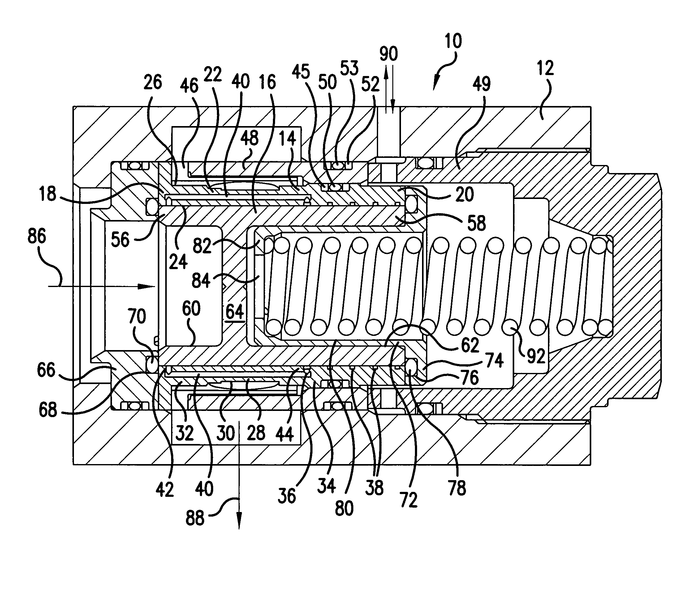
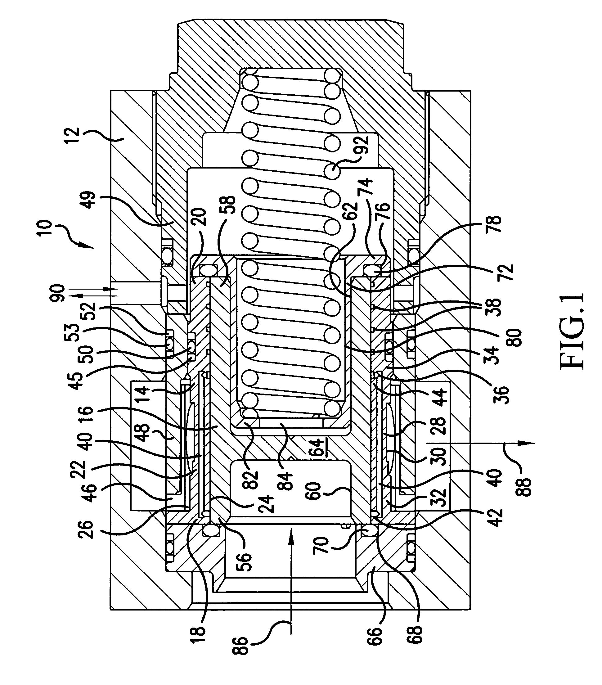
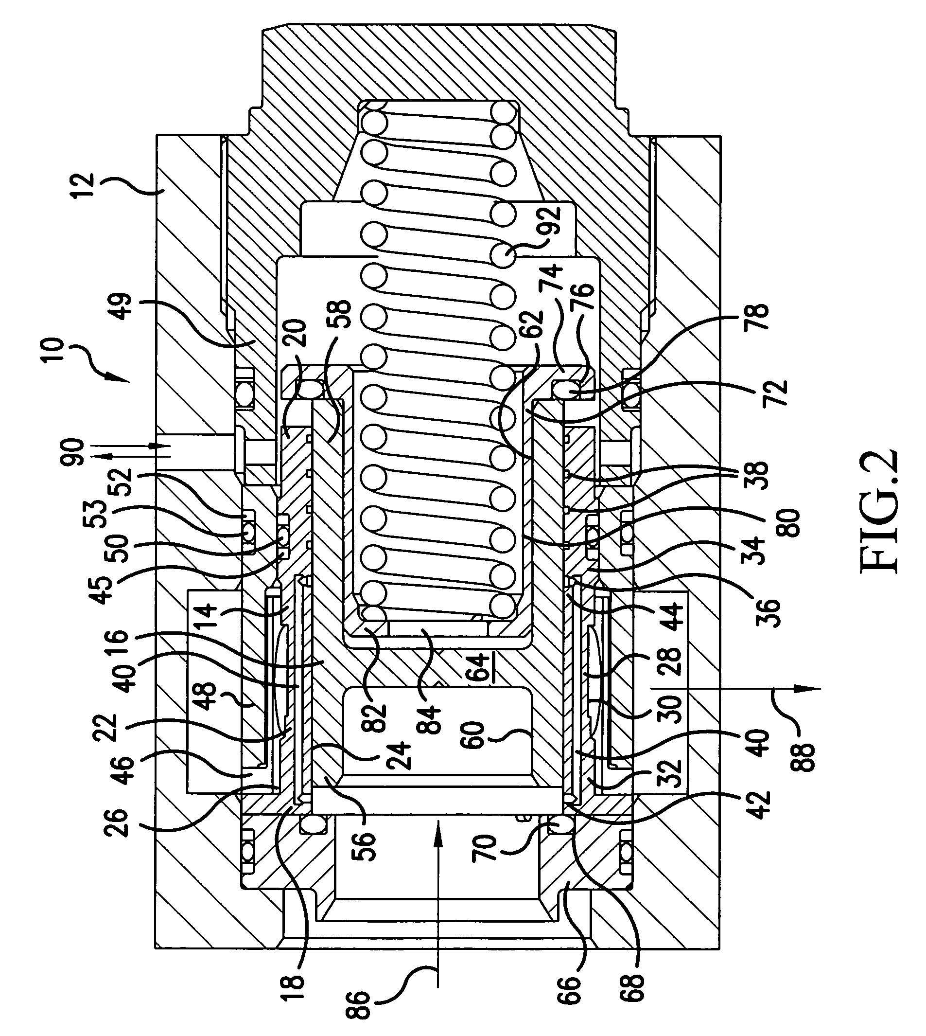
[0029]the subject invention is shown in FIG. 5 wherein like numerals are used to identify parts identical to the first embodiment. Valve assembly 100 shown in FIG. 3 includes a valve body 102 having a first bore 104 in a first end 106 substantially shallower that first bore 60 in the valve body 16 of the first embodiment, and a second bore 108 in a second end 110 of the valve body 102 that is substantially deeper than second bore 62 of valve body 16 of the first embodiment. In this embodiment, the seal seat 112 includes an end wall 114 that, unlike end wall 82 of the upper seal seat 72 of the first embodiment, lacks a through opening. Pressure channels 116 are provided in the side walls of valve body 102. This embodiment ports the relatively low outlet pressure 88 between the seal seat 112 and the valve body 102. The low pressure in this area increases the clamping force between the seal seat 112 and the valve body 102, as well as, improving the seal retention and valve deflection.


PUM


Abstract

A high pressure valve assembly (10) comprising a valve sleeve (14) and a valve body (16) slidably mounted in the valve sleeve (14) is disclosed, the valve body (16) and valve sleeve (14) each having first ends (18, 56) and second ends (20, 58). A sidewall (22) extends between the valve sleeve first end (18) and second end (20) which sidewall (22) has an inner surface (24) and an outer surface (26) and at least one opening (30) therethrough. The sidewall (22) also includes at least one channel (40) having a first end (42) facing the inner surface (24) at a first location closer to the first valve sleeve end (18) than to the second valve sleeve end (20) and a second end (44) facing the inner surface (24) at a second location closer to the second valve sleeve end (20) than to the first valve sleeve end (18). A method of using the valve assembly (10) is also disclosed.

Description

CROSS-REFERENCE TO RELATED APPLICATIONS[0001]The present application claims the benefit of U.S. Provisional Patent Application No. 60 / 492,301, filed Aug. 5, 2003, the entire contents of which is hereby incorporated by reference.[0002]This invention was made with Government support under Contract No. N00019-02-C-3003 awarded by the United States Navy. The Government has certain rights in this invention.FIELD OF THE INVENTION[0003]This invention relates to a valve for high pressure applications, and, more specifically, to a valve for a high pressure fluid metering system that reduces matched clearance leakage between a valve body and a valve sleeve.BACKGROUND OF THE INVENTION[0004]Fluid metering systems requiring high accuracy flow, such as fuel metering systems for gas turbine engines, often use a servo-controlled throttling valve to maintain a constant pressure delta (head pressure) across a metering orifice. In such systems, a supply of burn fuel is directed against a first side of...

Claims


Application Information

Patent Timeline
Patent Type & Authority Patents(United States)
IPC IPC(8): F02C7/232F02C9/26G05D7/01G05D16/10
CPCF02C9/263G05D16/106G05D16/18G05D16/187Y10T137/86734Y10T137/7868Y10T137/7925
Inventor LEWIS, STEVEN A.
Owner HONEYWELL INT INC
Why Eureka
Try Eureka