Casing shoes and methods of reverse-circulation cementing of casing

a cementing casing and shoe technology, applied in the field of cementing casings, to achieve the effect of reducing flow

Active Publication Date: 2008-01-29
HALLIBURTON ENERGY SERVICES INC
View PDF147 Cites 245 Cited by
  • Summary
  • Abstract
  • Description
  • Claims
  • Application Information

AI Technical Summary

Benefits of technology

[0006]The invention provides a method of cementing casing in a well bore, the method having the following steps: running a circulation valve comprising a reactive material into the well bore on the casing; reverse-circulating an activator material in the well bore until the activator material contacts the reactive material of the circulation valve; reconfiguring the circulation valve by contact of the activator material with the reactive material; and reverse-circulating a cement composition in the well bore until the reconfigured circulation valve decreases flow of the cement composition.
[0008]Another aspect of the invention provides a method of cementing casing in a well bore, the method having: running a circulation valve comprising a reactive material and a protective material into the well bore on the casing; reverse-circulating an activator material in the well bore until the activator material contacts the protective material of the circulation valve, wherein the activator material erodes the protective material to expose the reactive material; reconfiguring the circulation valve by exposing the reactive material to a well bore fluid; and reverse-circulating a cement composition in the well bore until the reconfigured circulation valve decreases flow of the cement composition.

Problems solved by technology

This may be because, if an undesirable amount of a cement composition enters the inner diameter of the casing, once set it typically has to be drilled out before further operations are conducted in the well bore.

Method used


Image

  • Casing shoes and methods of reverse-circulation cementing of casing
  • Casing shoes and methods of reverse-circulation cementing of casing
  • Casing shoes and methods of reverse-circulation cementing of casing

Examples


Embodiment Construction

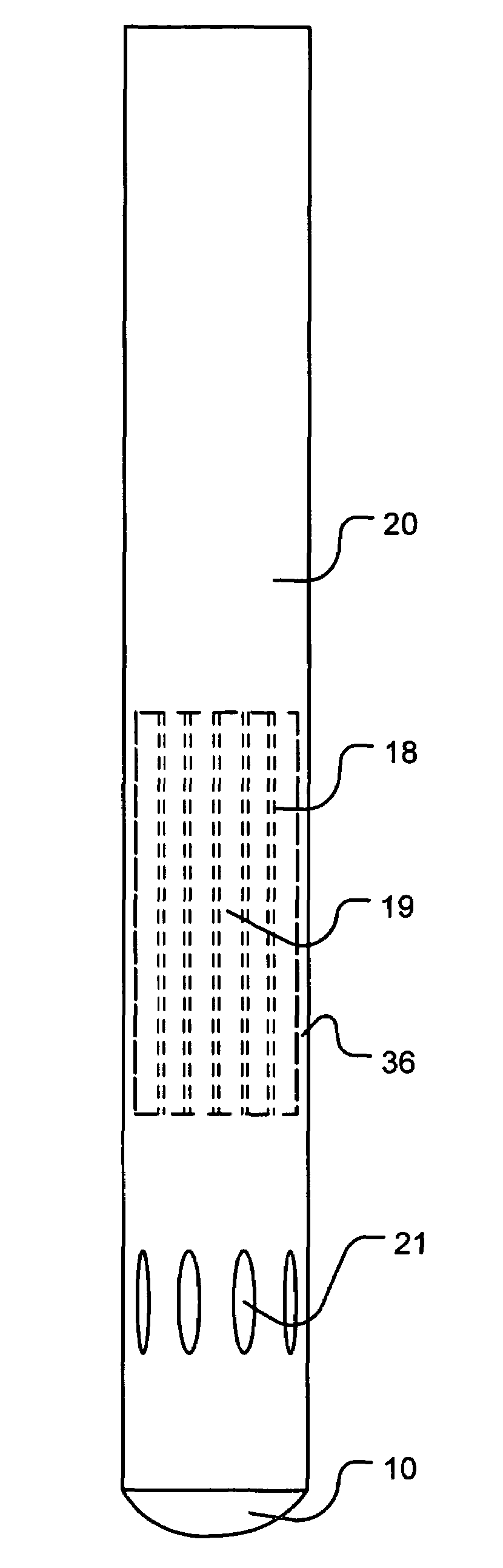
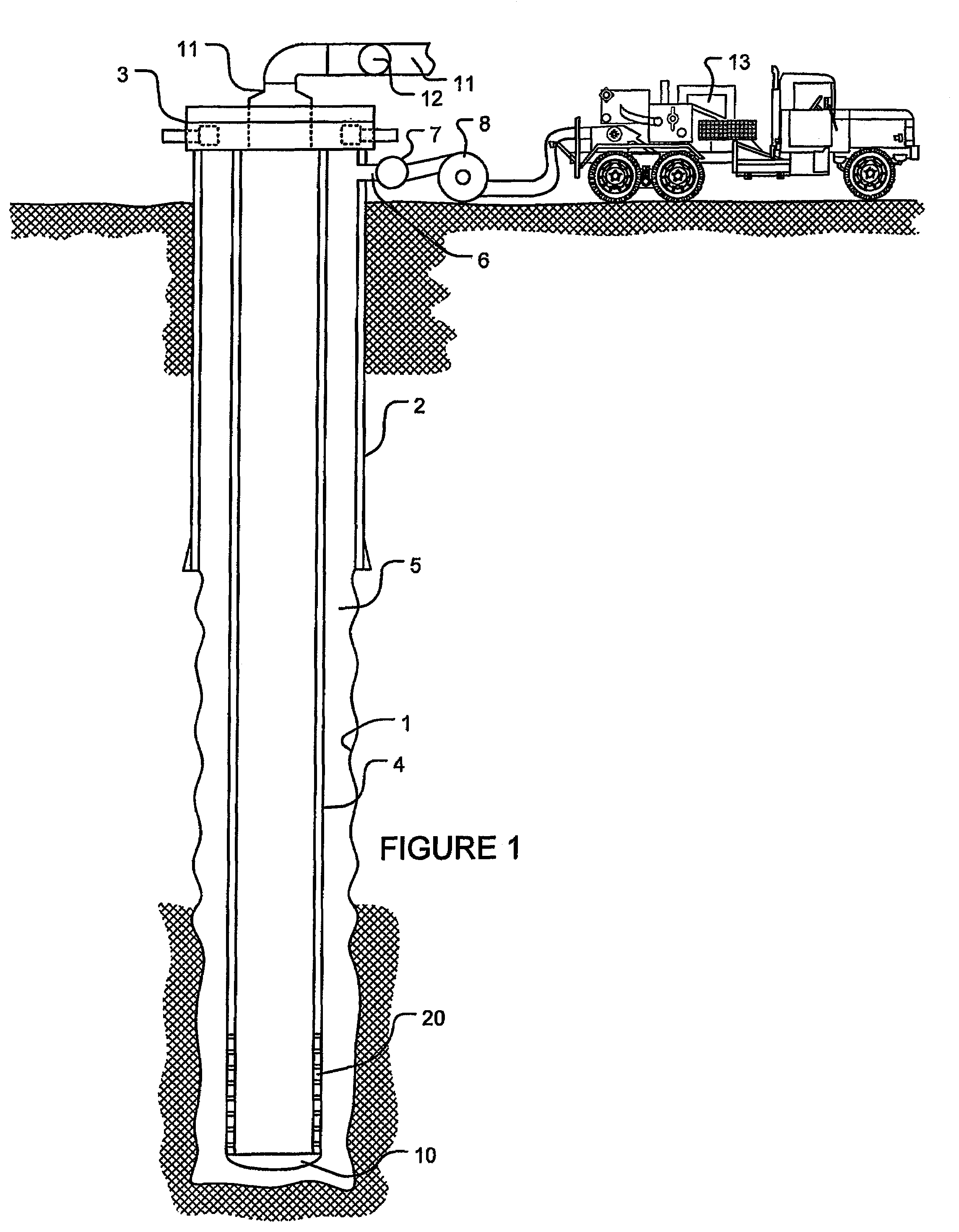
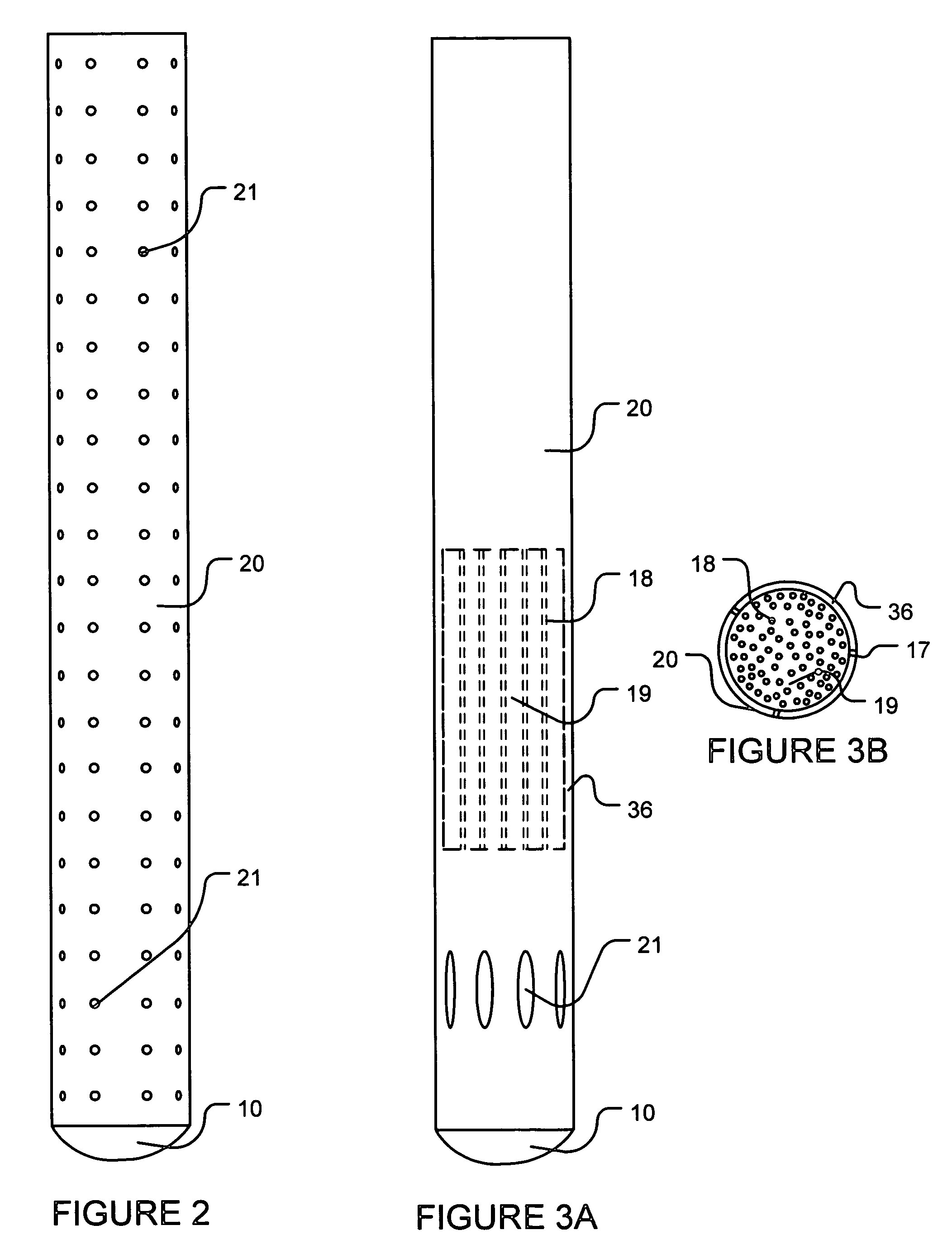
[0054]Referring to FIG. 1, a cross-sectional side view of a well bore is illustrated. In particular, surface casing 2 is installed in the well bore 1. A well head 3 is attached to the top of the surface casing 2 and casing 4 is suspended from the well head 2 and the well bore 1. An annulus 5 is defined between the well bore 1 and the casing 4. A casing shoe 10 is attached to the bottom most portion of the casing 4. A feed line 6 is connected to the surface casing 2 to fluidly communicate with the annulus 5. The feed line 6 has a feed valve 7 and a feed pump 8. The feed line 6 may be connected to a cement pump truck 13. The feed line 6 may also be connected to vacuum truck, a stand alone pump or any other pumping mechanism known to persons of skill. A return line 11 is connected to the well head 3 so as to fluidly communicate with the inner diameter of the casing 4. The return line has a return valve 12. The casing 4 also comprises a circulation valve 20 near the casing shoe 10. When...


PUM

PropertyMeasurementUnit
mean sizeaaaaaaaaaa
pHaaaaaaaaaa
temperaturesaaaaaaaaaa

Abstract

A method having the following steps: running a circulation valve comprising a reactive material into the well bore on the casing; reverse-circulating an activator material in the well bore until the activator material contacts the reactive material of the circulation valve; reconfiguring the circulation valve by contact of the activator material with the reactive material; and reverse-circulating a cement composition in the well bore until the reconfigured circulation valve decreases flow of the cement composition. A circulation valve for cementing casing in a well bore, the valve having: a valve housing connected to the casing and comprising a reactive material; a plurality of holes in the housing, wherein the plurality of holes allow fluid communication between an inner diameter of the housing and an exterior of the housing, wherein the reactive material is expandable to close the plurality of holes.

Description

BACKGROUND OF THE INVENTION[0001]This invention relates to cementing casing in subterranean formations. In particular, this invention relates to methods for cementing a casing annulus by reverse-circulating the cement composition into the annulus without excessive cement composition entering the casing inner diameter.[0002]It is common in the oil and gas industry to cement casing in well bores. Generally, a well bore is drilled and a casing string is inserted into the well bore. Drilling mud and / or a circulation fluid is circulated through the well bore by casing annulus and the casing inner diameter to flush excess debris from the well. As used herein, the term “circulation fluid” includes all well bore fluids typically found in a well bore prior to cementing a casing in the well bore. Cement composition is then pumped into the annulus between the casing and the well bore.[0003]Two pumping methods have been used to place the cement composition in the annulus. In the first method, t...

Claims


Application Information

Patent Timeline
Patent Type & Authority Patents(United States)
IPC IPC(8): E21B33/14
CPCE21B21/10E21B33/14E21B34/102
Inventor BADALAMENTI, ANTHONY M.TURTON, SIMONBLANCHARD, KARL W.FAUL, RONALD R.CROWDER, MICHAEL G.ROGERS, HENRY E.GRIFFITH, JAMES E.REDDY, B. RAGHAVA
Owner HALLIBURTON ENERGY SERVICES INC
Why Eureka
Try Eureka