Tubing expansion

a technology of tubing and expansion tube, which is applied in the direction of fluid removal, earthwork drilling and mining, borehole/well accessories, etc., can solve the problems of reducing the service life of the seal, and reducing the difficulty of achieving satisfactory results. , to achieve the effect of extending the seal life, avoiding the loss of sealing function, and facilitating the formation of seal

Inactive Publication Date: 2008-01-29
WEATHERFORD TECH HLDG LLC
View PDF32 Cites 14 Cited by
  • Summary
  • Abstract
  • Description
  • Claims
  • Application Information

AI Technical Summary

Benefits of technology

[0026]Preferably, the tool includes a leading tubing treating or conditioning portion, and most preferably the tubing treating portion is provided in combination with a seal member. Thus, the tubing treating portion may clean the tubing ahead of the seal member, for example removing scale and the like, thus facilitating formation of a seal between the seal member and the tubing, and extending seal life. Preferably, the treating portion is adapted to expand or reform the tubing to a predetermined diameter, to match the seal member, and thus assists in avoiding loss of sealing function where the tubing to be expanded is oval is dented or otherwise has an irregular form. Most preferably, the tubing treating portion is adapted to provide a compliant expansion or reforming function, that is the portion does not define a fixed diameter and is thus capable of negotiating or passing immovable restrictions. Furthermore, the tubing treating portion is preferably spaced from the expansion member when the member is in the second configuration and thus acts to stabilize the expansion member and facilitates straight and consistent expansion; in the absence of such stabilization the expansion member may tend to deviate from the tubing axis as it is translated through the bore, with the result that there is a loss of cylindricality. This feature may also be used to advantage in combination with other forms of expansion member or expansion device, and the stabilization of the expansion member may be of particular assistance in expanding tubing which is differentially stuck in a bore. In such cases, the portion of the tubing wall which is pressed against the bore wall will often experience less extension or deformation than the remainder of the wall, which may result in undesirable thinning or extension of the remainder of the wall. By stabilizing the expansion process by providing the leading conditioning or treating portion this problem may be obviated or mitigated. Without wishing to be bound by theory, it is believed the leading conditioning portion assists in lifting the tubing clear of the bore wall before expansion takes place.

Problems solved by technology

Numerous proposals have been put forward for apparatus and methods for implementing this complex procedure, however difficulties remain in achieving a satisfactory solution to a number of problems, in particular in hanging the tubular off the casing, cementing the tubular, and sealing the tubular to the casing.
However, the difficulties relating to providing adequate hanging support, sealing and cementing remain.

Method used


Image

  • Tubing expansion
  • Tubing expansion
  • Tubing expansion

Examples


Embodiment Construction

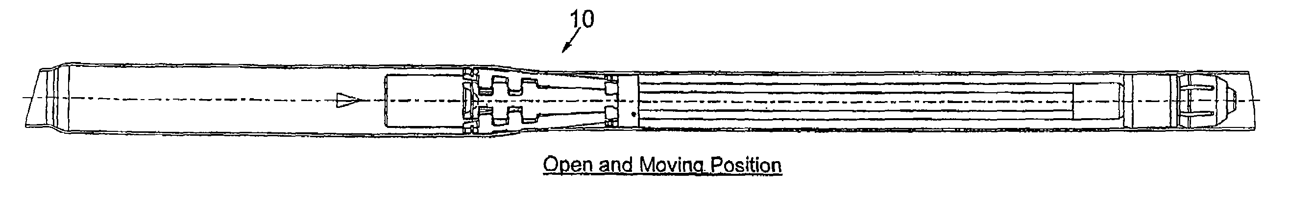
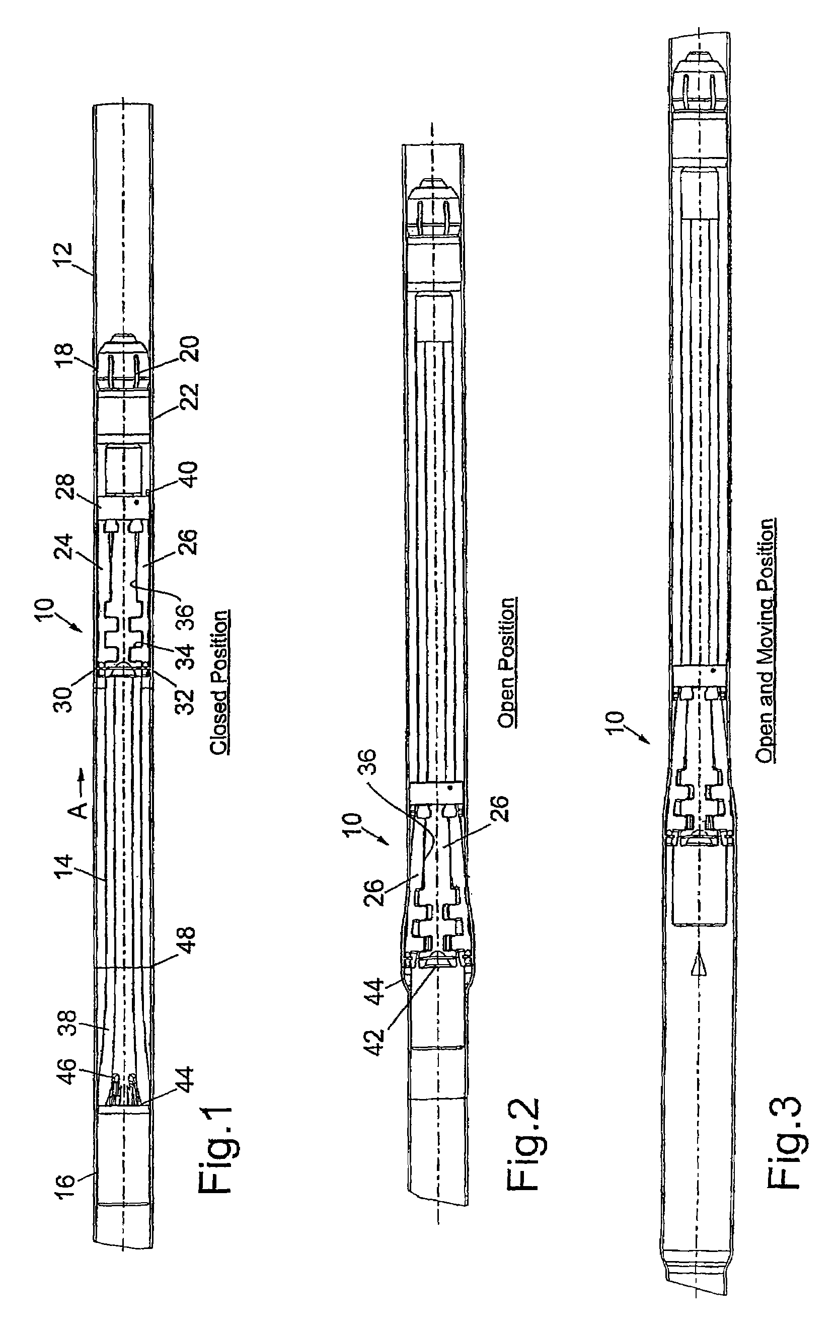
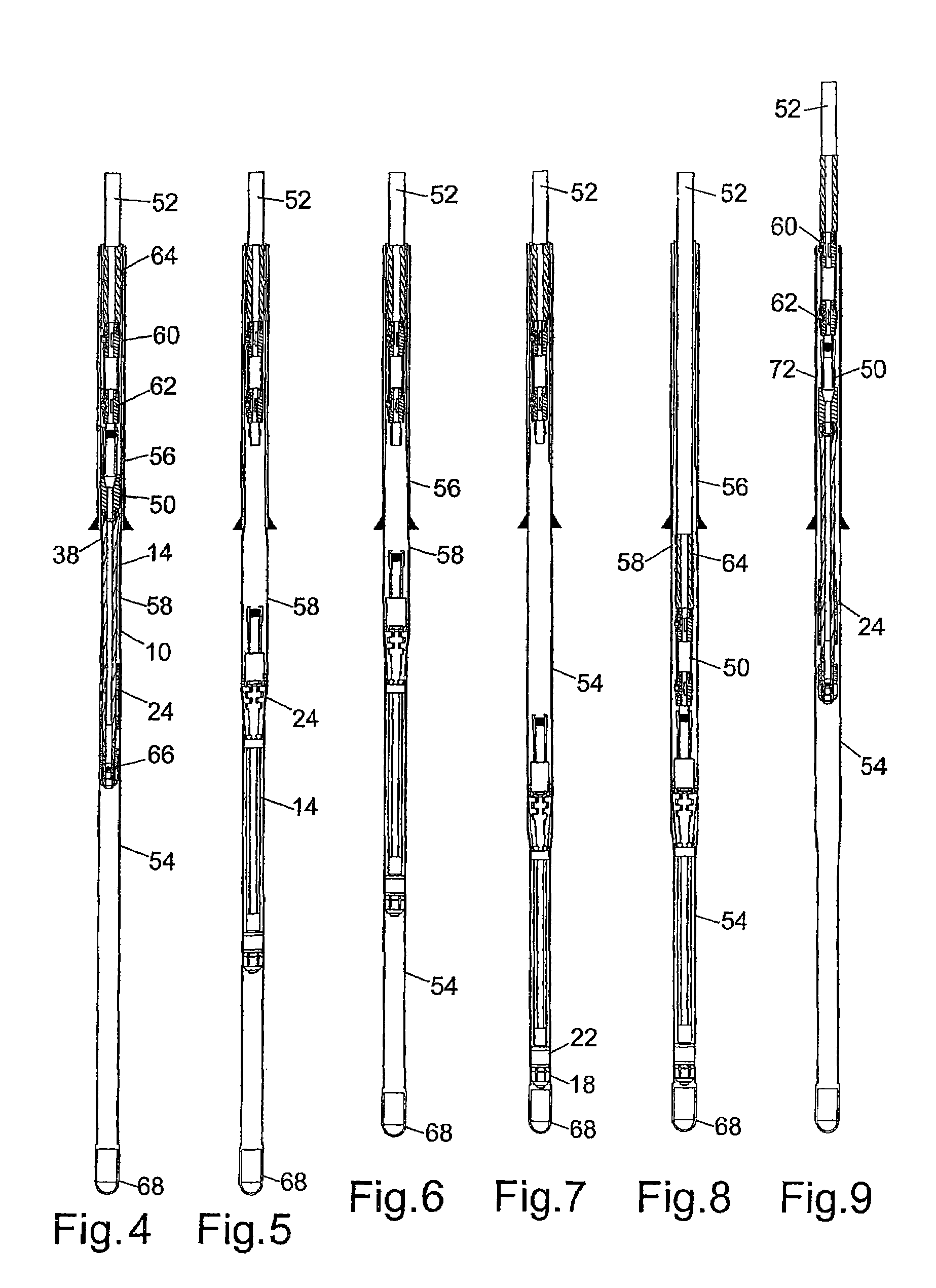
[0033]Reference is first made to FIG. 1 of the drawings, which illustrates a tubing expansion tool 10 in accordance with a preferred embodiment of one aspect of the present invention. The tool 10 is shown in a closed first configuration in FIG. 1, while FIGS. 2 and 3 of the drawings show the tool 10 in an open second configuration, and being used to expand a section of downhole tubing 12. Following a description of the tool 10, with reference to FIGS. 1, 2 and 3, the use of the tool 10 in a tubing expansion operation will be described with reference to FIGS. 4 to 9 of the drawings.

[0034]The tool 10 comprises a mandrel 14 having a connector 16 at one end to allow the tool 10 to be releasably mounted at the lower end of a tool string. As will be described, the connector 16 incorporates an internal fishing profile, to allow retrieval of the tool 10 following a tubing expansion operation.

[0035]Mounted to the lower or leading end of the mandrel 14 is a compliant expansion cone 18. The co...


PUM

PropertyMeasurementUnit
diameteraaaaaaaaaa
radius of curvatureaaaaaaaaaa
circumferenceaaaaaaaaaa

Abstract

An apparatus and a method for expanding a downhole tubular. The apparatus includes a mandrel defining at least one curved support surface. The apparatus further includes an expansion member defining a curved bearing surface for contact with the support surface and corresponding to the mandrel support surface. The expansion member is movable relative to the mandrel, whereby the surfaces are in contact and movable over one another to move the expansion member from a smaller diameter first configuration towards a larger diameter second configuration.

Description

CROSS-REFERENCE TO RELATED APPLICATIONS[0001]This application claims benefit of Great Britain patent application serial number 0304335.3, filed Feb. 26, 2003, which is herein incorporated by reference.BACKGROUND OF THE INVENTION[0002]1. Field of the Invention[0003]This invention relates to tubing expansion, and in particular to the expansion of downhole tubing, and to tools and apparatus for use in expanding downhole tubing.[0004]2. Description of the Related Art[0005]A recent significant development in the oil and gas exploration and production industry has been the introduction of expandable downhole tubing, that is bore-lining tubing that is run into a drilled bore and then expanded to a larger diameter. This has permitted the creation of monobore or near monobore wells, that is wells having a substantially constant diameter. This may be achieved by running a tubular through existing bore-lining casing and into a section of open or unlined bore below the casing, but with the uppe...

Claims


Application Information

Patent Timeline
Patent Type & Authority Patents(United States)
IPC IPC(8): E21B23/00B21D39/20E21B43/10
CPCB21D39/20E21B43/105E21B29/10E21B43/10E21B43/103
Inventor TRINDER, DUNCAN JAMESSIMPSON, NEIL ANDREW ABERCROMBIENICOLL, JOHN STRACHANMACKAY, GRAHAMMACKAY, ALEXANDER CRAIG
Owner WEATHERFORD TECH HLDG LLC
Why Eureka
Try Eureka