Pin grid array zero insertion force connectors configurable for supporting large pin counts

a pin array and connector technology, applied in the direction of electrical equipment, connection, coupling device connection, etc., can solve the problems of difficult to achieve a 50 mm50 mm array size, difficult to transport molten plastic from the injection port to all mold areas, and difficulty in achieving uniformity and flatness of injection molding parts, etc., to achieve a wider i/o pin count and fine pitch

Inactive Publication Date: 2008-01-29
GLOBALFOUNDRIES INC
View PDF6 Cites 6 Cited by
  • Summary
  • Abstract
  • Description
  • Claims
  • Application Information

AI Technical Summary

Benefits of technology

[0006]The present invention, in illustrative embodiments thereof, meets the above-noted need by providing a PGA-type socket which overcomes certain characteristic limitations associated with conventional PGA interconnections. The illustrative PGA socket has a finer pitch compared to standard PGA sockets, thereby allowing the PGA socket to receive integrated circuits (ICs) having larger I / O pin counts than what would have otherwise been achievable using conventional means. To accomplish this, in accordance with illustrative embodiments of the invention, two or more sub-socket components having a finer pitch (e.g., less than about 1.27 mm) are beneficially combined to form a larger effective ZIF PGA socket adapted to provide an electrical interconnection with large I / O pin count ICs. Each of the sub-socket components is configured to mechanically engage at least one of the other sub-socket components so that electrical connection between individual pins of an IC received by the socket and corresponding contacts of the socket are made at substantially the same time.

Problems solved by technology

PGA suppliers are now attempting to fabricate PGA sockets that have a large I / O count at a 1.00 mm pitch, but are struggling to achieve a 50 mm×50 mm array size.
For example, injection molding parts with sufficient uniformity and flatness is difficult, in part because the large area of a 50 mm×50 mm array makes the transport of molten plastic from the injection ports to all mold areas difficult and in part from shrinkage and thermally induced stress across the array.

Method used


Image

  • Pin grid array zero insertion force connectors configurable for supporting large pin counts
  • Pin grid array zero insertion force connectors configurable for supporting large pin counts
  • Pin grid array zero insertion force connectors configurable for supporting large pin counts

Examples


Embodiment Construction

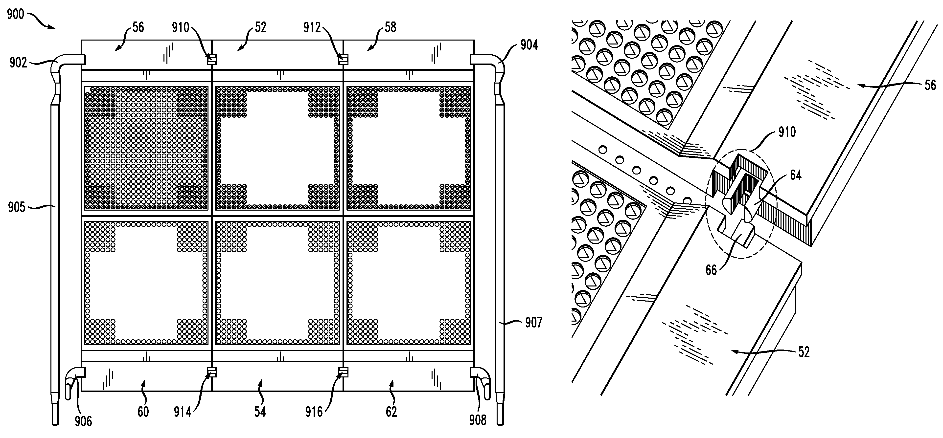
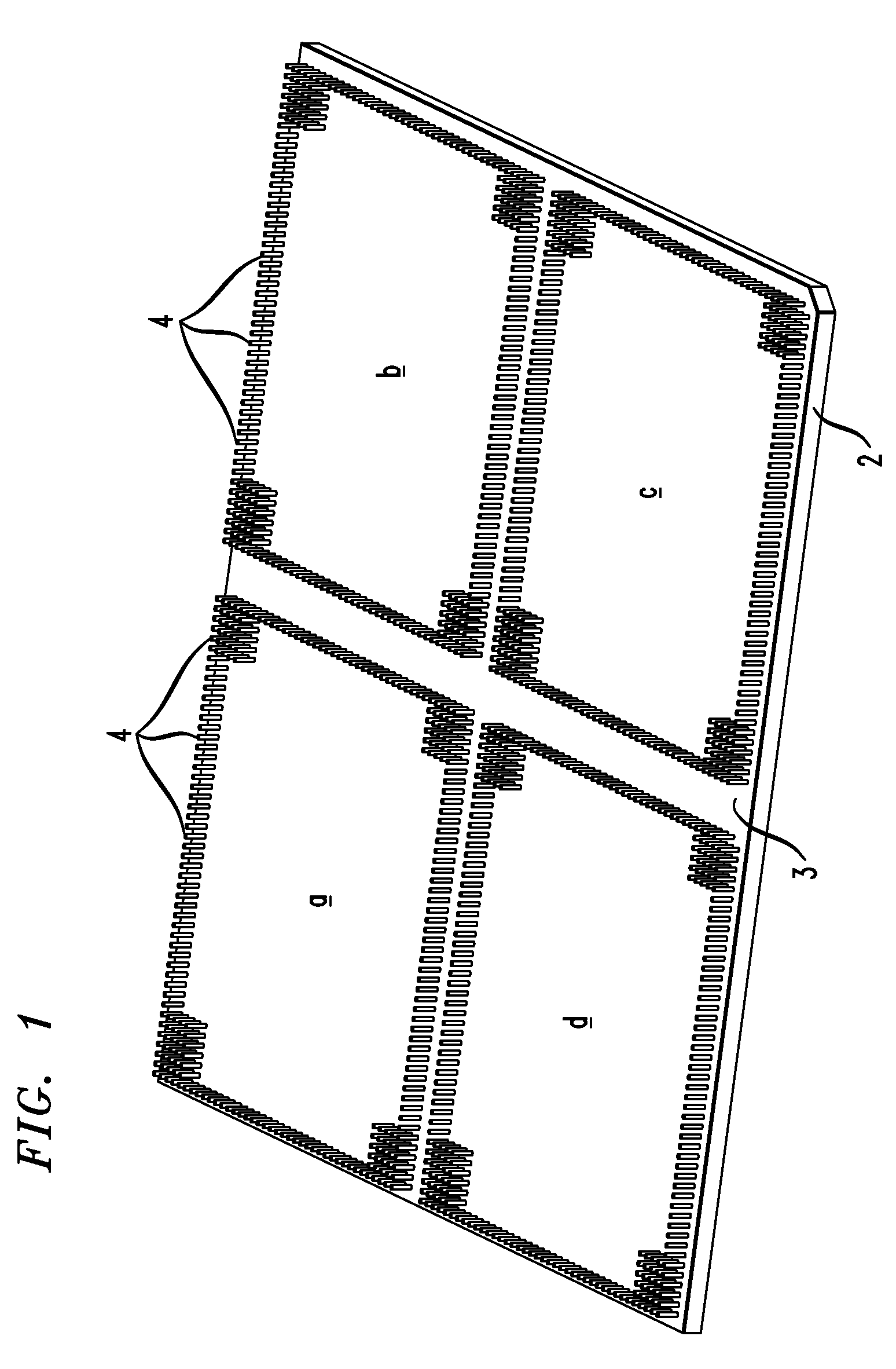
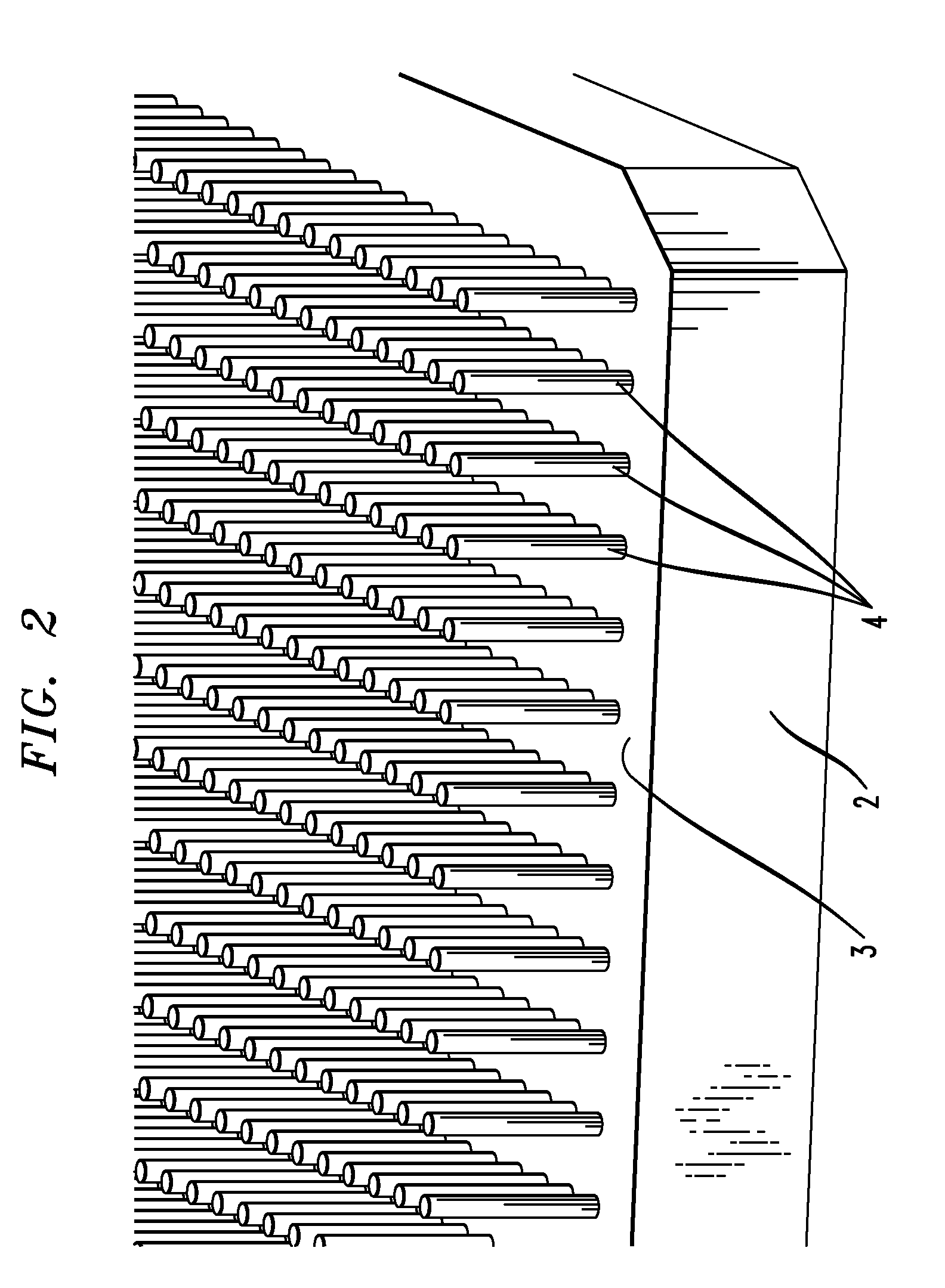
[0020]The present invention will be described herein in the context of illustrative embodiments of a ZIF PGA socket. It should be understood, however, that the present invention is not limited to the particular PGA socket arrangements shown. Rather, the present invention provides techniques for advantageously overcoming certain characteristic limitations of conventional PGA interconnections. The illustrative ZIF PGA socket has a finer pitch compared to standard PGA sockets, thereby allowing the PGA socket to receive ICs having larger I / O pin counts than what would have otherwise been achievable using conventional methodologies. The PGA socket formed in accordance with embodiments of the present invention is particularly well-suited for use in a wide variety of IC applications, such as, for example, applications involving the interconnection of high pin count ICs with a printed wiring board.

[0021]Small pitch PGA sockets (e.g., about 1.27 mm or less) are sometimes referred to as micro...


PUM


Abstract

A PGA socket including a plurality of sub-socket components, which when used in combination forms a larger effective socket, includes multiple apertures configured to receive corresponding pins of an IC. The PGA socket further includes multiple contact members, each of the contact members corresponding to a respective one of the apertures. The contact members are configured to movably engage corresponding pins of the IC upon respective movement of the apertures so as to provide electrical and mechanical contact thereto. Each of the sub-socket components is configured to mechanically engage at least one of the other sub-socket components such that the contact members in each of the sub-socket components are capable of electrically connecting to corresponding pins of the IC substantially simultaneously.

Description

FIELD OF THE INVENTION[0001]The present invention relates generally to area array microelectronic interconnections, and more particularly relates to pin grid array type area interconnections.BACKGROUND OF THE INVENTION[0002]Pin grid arrays (PGAs) are commonly used in the microelectronics industry, for example, for connecting a chip module to a printed circuit board or printed wiring board, utilizing pins in an area under the module that plug into a corresponding socket on the printed circuit board. Alternatively, the module may utilize a socket in an area under the module which is adapted for receiving corresponding pins mounted on the printed circuit board. PGAs are commonly, although not always, referred to as zero insertion force (ZIF) connectors. The term “ZIF connector” generally refers to a socket arrangement wherein when the socket is open, a chip may be placed in the socket without any pressure at all, and when the socket is then closed, the contacts of the socket grip the p...

Claims


Application Information

Patent Timeline
Patent Type & Authority Patents(United States)
IPC IPC(8): H01R4/50
CPCH05K7/1007H01R13/193
Inventor HOUGHAM, GARETH GEOFFREYBRODSKY, WILLIAM LOUISCIPOLLA, THOMAS M.COTEUS, PAUL WILLIAMMALFATT, RONALD
Owner GLOBALFOUNDRIES INC
Why Eureka
Try Eureka