Elongated Conductors and Methods of Making and Using the Same

Active Publication Date: 2016-12-01
AUTONOMIX MEDICAL
View PDF7 Cites 20 Cited by
  • Summary
  • Abstract
  • Description
  • Claims
  • Application Information

AI Technical Summary

Benefits of technology

[0005]Elongated conductors are provided. Aspects of the elongated conductors include: an elongated structure having a proximal region and a distal region, where the elongated conductor includes two or more insulated conducting members that are in fixed relative position along at least a portion of the elongated structure and e

Problems solved by technology

This manufacturing protocol is

Method used


Image

  • Elongated Conductors and Methods of Making and Using the Same
  • Elongated Conductors and Methods of Making and Using the Same
  • Elongated Conductors and Methods of Making and Using the Same

Examples


Example

Example 1

Production of Elongated Conductor with 12 Conducting Members

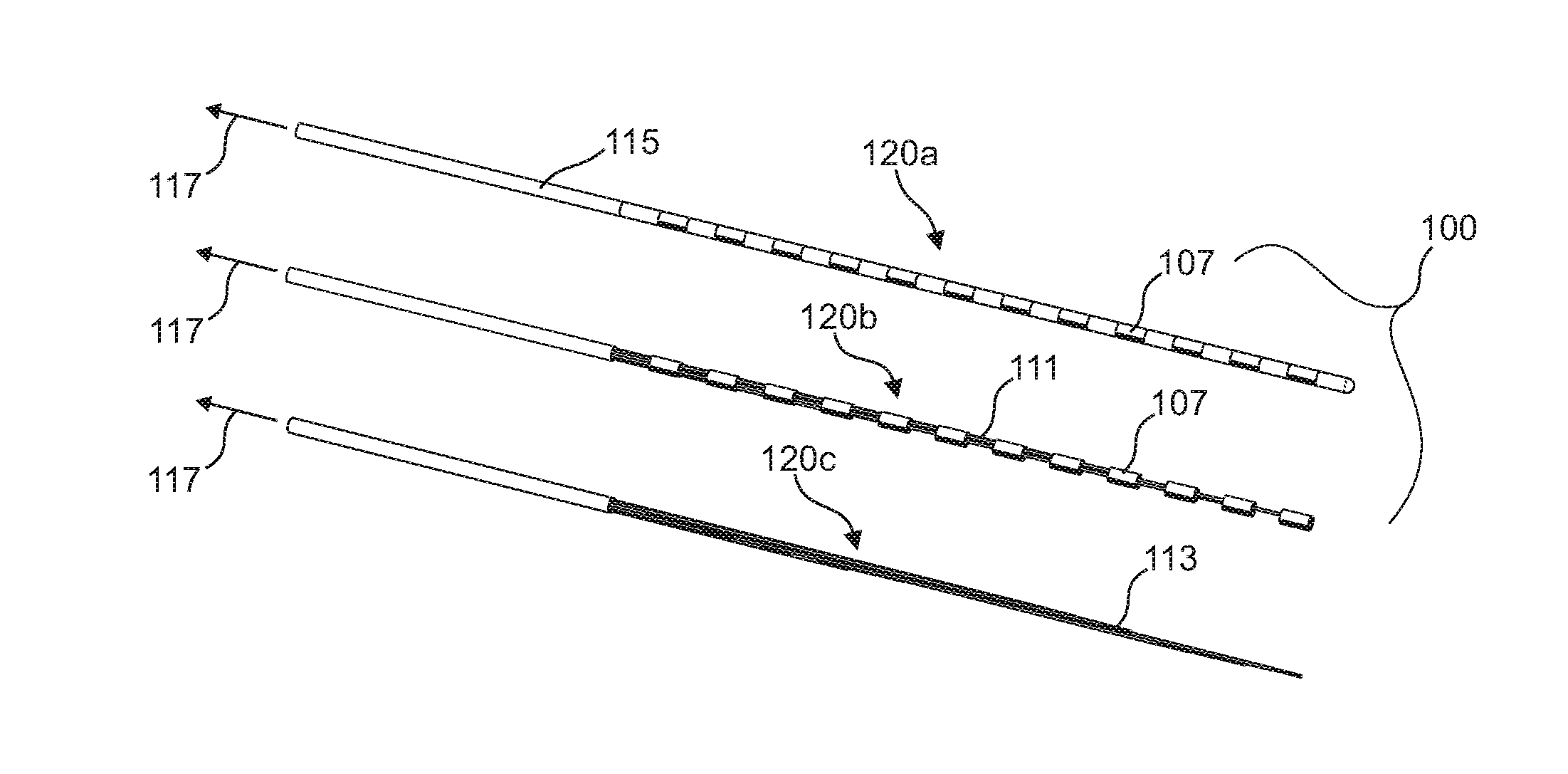
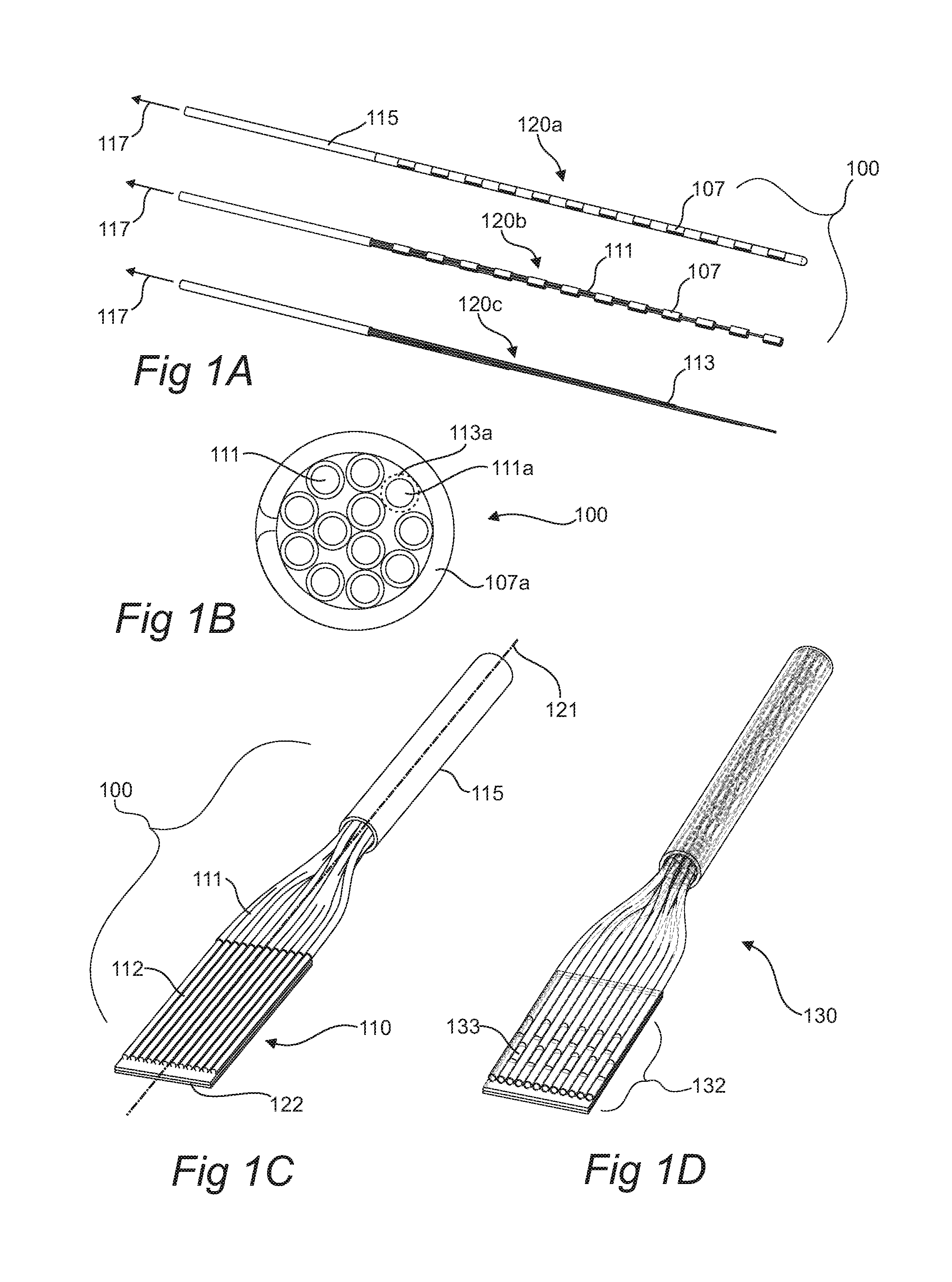
[0120]An elongated conductor with 12 conducting members is formed. The conducting members are formed from a copper alloy (with nominal diameter of approximately 25 μm) with a first polyimide insulation layer (with thickness of approximately 3.5 μm) and a second polyvinyl butyral binding layer (with thickness of approximately 3 μm). The conducting members are arranged along a horizontal plane with approximately 0.5 mm spacing between individual conducting members, and the proximal and distal encoded windows are formed in the polyimide and polyvinyl butyral layers with an ultraviolet laser ablation source. In this non-limiting instance, the distal encoded windows are patterned so as to form a 2D array of windows (for later attachment to a planar component as a single connector) with windows substantially oriented to one side of the working plane, and the proximal encoded windows are patterned so as to form a substant...

Example

Example 2

Production of Elongated Conductor with Distal Split Configuration

[0124]The same procedure is followed up until the step of attaching the distal region to the support. Instead the distal region is broken into two groups of 6 conducting members, and each of the groups is attached to a separate support so as to form a split arrangement. The total width of each split arrangement is 238 μm (40 μm pitch between conducting members). An additional 4 mm long length of the split regions is clamped before proceeding with the winding step outlined in Example 1. The split distal patterns are then attached to each side of an HDI flex circuit, so as to form a robust interconnect with a narrow overall width of 245 um. An ultra-thin walled polymer sheath is placed around the distal region to bridge across the hypotube to form a low profile distal part of the assembly. The distal region is potted with a silicone adhesive to form a secure structure at the distal end of the assembly.

Example

Example 3

Elongated Conductor with Flexible Shield

[0125]An elongated conductor with 12 conducting members and a flexible shield is formed. The conducting members are formed from a copper alloy (with nominal diameter of approximately 25 μm) with a first polyimide insulation layer (with thickness of approximately 3.5 μm) and a second polyvinyl butyral binding layer (with thickness of approximately 3 μm). The conducting members are arranged along a horizontal plane with approximately 0.5 mm spacing between individual conducting members, and the proximal and distal encoded windows are formed in the polyimide and polyvinyl butyral layers with an ultraviolet laser ablation source. In this non-limiting instance, the distal encoded windows are patterned so as to form a 2D array of windows (for later attachment to a planar component as a single connector) with windows substantially oriented to one side of the working plane, and the proximal encoded windows are patterned so as to form a substa...


PUM


Abstract

Elongated conductors are provided. Aspects of the elongated conductors include: an elongated structure having a proximal region and a distal region, where the elongated conductor includes two or more insulated conducting members that are in fixed relative position along at least a portion of the elongated structure and extend from the proximal region to the distal region. A pattern of insulation openings among the insulated conducting members is present at one or both of the proximal and distal regions. Aspects of the invention further include methods of making the elongated conductors, as well as devices that include the elongated conductors.

Description

CROSS-REFERENCE TO RELATED APPLICATIONS[0001]Pursuant to 35 U.S.C. §119 (e), this application claims priority to the filing date of the U.S. Provisional Patent Application Ser. No. 62 / 169,347, filed Jun. 1, 2015, the disclosure of which is incorporated herein by reference.INTRODUCTION[0002]Elongated conductors, such as elongated electrical conductors, find use in a variety of different devices used in many aspects of everyday life. For example, elongated electrical conductors find use a variety of medical devices, including interventional, minimally invasive, surgical and implantable devices. Medical devices currently in use include “smart” sensing and therapeutic guidewires, which may include a sensor (pressure, thermocouple, etc.) and therapeutic technology located at the tip of a guidewire. In such devices, 2 or 3 wires are generally necessary to interface with the sensor. The sensor is most often a simple bridge based sensor, or a variable resistance based sensor, etc.[0003]Anot...

Claims


Application Information

Patent Timeline
IPC IPC(8): H01B7/02A61B5/00H01B13/00H01B7/17H05K9/00
CPCH01B7/02H01B7/17A61B5/6876H01B13/0036H05K9/0098A61B5/6852A61B2562/222A61N1/05A61B18/1492A61N1/0488H01B13/06H01B7/0892A61B2017/00526A61B2018/00178A61B2562/125A61M25/00H01B7/0846
Inventor TOTH, LANDYSCHWARTZ, ROBERT
Owner AUTONOMIX MEDICAL
Why Eureka
Try Eureka