Biosensor and measuring method using the same

a biosensor and measuring method technology, applied in the field of biosensors, can solve the problems of large scale of the measuring system, inability to simultaneously measure, and complicated maintenan

Active Publication Date: 2008-01-29
PHC HLDG CORP
View PDF10 Cites 132 Cited by
  • Summary
  • Abstract
  • Description
  • Claims
  • Application Information

AI Technical Summary

Problems solved by technology

However, if the appropriate pHs of the enzymes for the plurality of specific substances to be measured or the appropriate kinds of buffer solutions are different, simultaneous measurement is impossible.
Also, the measuring system becomes large-scale, and the maintenance becomes complicated.
Further, since simultaneous measurement is not possible, the sample solutions evaporate with passage of time, which may result in a decreased measuring accuracy.
Further, the above-described biosensor having a plurality of elec

Method used


Image

  • Biosensor and measuring method using the same
  • Biosensor and measuring method using the same
  • Biosensor and measuring method using the same

Examples


embodiment 1

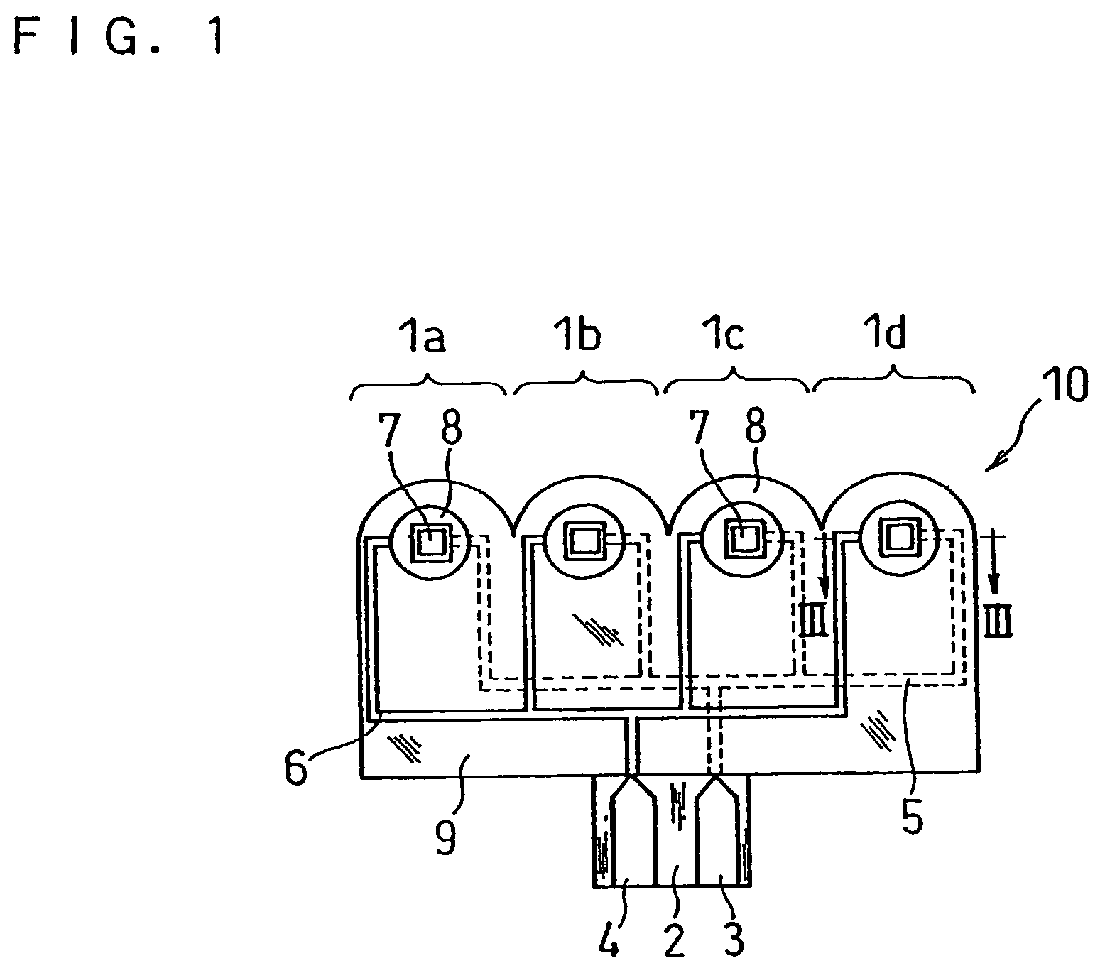
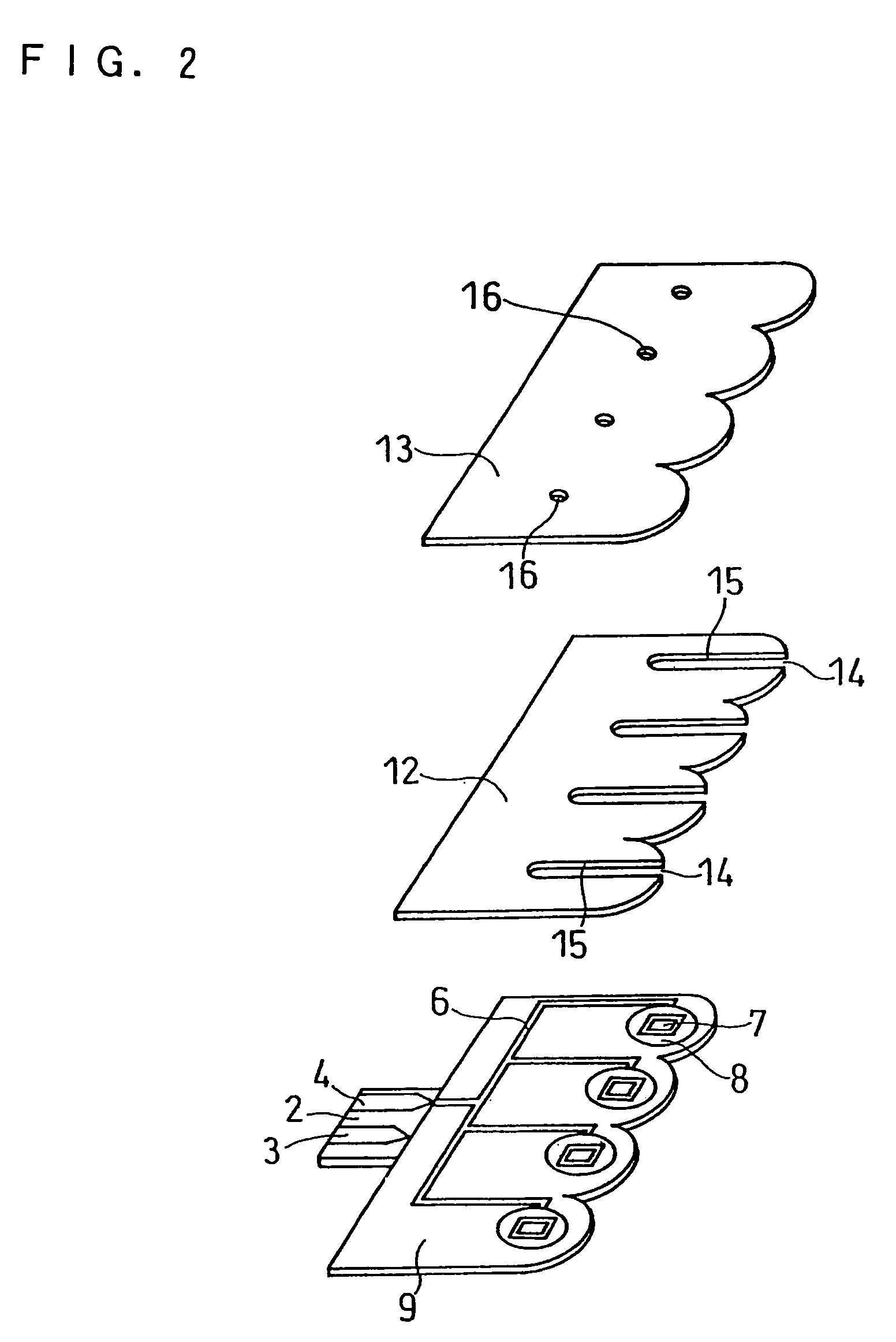
[0049]FIG. 1 is a plane view of a biosensor in Embodiment 1 from which the spacer and cover are omitted. FIG. 2 is a decomposed perspective view of the biosensor from which the reagent system and controlling system are omitted. FIG. 3 contains sectional views taken on line III—III of FIG. 1, showing processes of forming an electrode system. FIG. 4 is a sectional view of the biosensor with the reagent system and controlling system taken on line III—III of FIG. 1.

[0050]A biosensor 10 of this embodiment is produced as follows. First, a silver paste is printed on a base plate 2 made of an insulating resin by screen printing to form a working electrode terminal 3 and a working electrode lead 5 having 4 branches, as illustrated in FIG. 3 (b). Next, a conductive carbon paste containing a resin binder is printed to form 4 working electrodes 7, as illustrated in FIG. 3 (c). Subsequently, an insulating paste is printed to form an insulating layer 9, as illustrated in FIG. 3 (d). Further, a si...

embodiment 2

[0064]FIG. 5 is a plane view of a biosensor in Embodiment 2 from which the spacer and cover are omitted. FIG. 6 is a decomposed perspective view of the biosensor from which the reagent system and controlling system are omitted. FIG. 7 contains sectional views taken on line VII—VII of FIG. 5, showing processes of forming an electrode system. FIG. 8 is a sectional view of the biosensor with the reagent system and controlling system taken on line VII—VII of FIG. 5.

[0065]A biosensor 20 of this embodiment is produced as follows. First, a silver paste is printed on a base plate 22 made of an insulating resin by screen printing to form 4 working electrode terminals 23, 4 counter electrode terminals 24, 4 working electrode leads 25, and 4 counter electrode leads 26, as illustrated in FIG. 7 (a). Next, a conductive carbon paste containing a resin binder is printed to form 4 working electrodes 27, as illustrated in FIG. 7 (b). Subsequently, an insulating paste is printed to form an insulating...

embodiment 3

[0074]FIG. 13 is a plane view of a biosensor in Embodiment 3 from which the spacer and cover are omitted. FIG. 14 is a decomposed perspective view of the biosensor from which the reagent system and controlling system are omitted.

[0075]A biosensor 50 of this embodiment is produced as follows. In the same manner as in Embodiment 1, a working electrode terminal 53, a working electrode lead 55 having 4 branches, 4 working electrodes 57, an insulating layer 59, a counter electrode terminal 54, a counter electrode lead having 4 branches 56, and 4 counter electrodes 58 are formed on a base plate 52. Subsequently, a reagent system is formed over the respective electrode systems. A spacer 62 of this embodiment has slits 65a, 65b, 65c , and 65d having different lengths for forming respective sample solution supply pathways of sensor units, and these slits communicate with one opening 64 which serves as a sample supply inlet. The spacer 62 and a cover 63 having four air vents 66 are bonded to ...


PUM

PropertyMeasurementUnit
Timeaaaaaaaaaa
Speedaaaaaaaaaa
Hydrophilicityaaaaaaaaaa

Abstract

A biosensor capable of measuring the concentration of one or more specific substances in one or more sample solutions almost simultaneously is provided. The biosensor comprises a plurality of sensor units, and each of the sensor units comprises an electrode system including a working electrode and a counter electrode on an insulating base plate and a reagent system including an oxidoreductase and an electron mediator. The biosensor is so configured that sample solutions supplied to the respective sensor units reach the respective reagent systems at different times. Specifically, each of the sensor units has a controlling system between a sample supply inlet and the reagent system, and the controlling system controls the time it takes for the sample solution to reach the reagent system from the sample supply inlet.

Description

BACKGROUND OF THE INVENTION[0001]The present invention relates to a biosensor for measuring the concentration of one or more specific substances contained in one or more sample solutions and a measuring method using the biosensor.[0002]As a conventional biosensor for measuring the concentrations of a plurality of specific substances simultaneously, there is a flow injection type biosensor. One such example is Flow Injection Analyzer (FIA) YSI MODEL 2700 SELECT (Yellow Spring Instrument Co., Inc.), which is a biosensor utilizing an immobilized enzyme membrane and electrode reaction, and its operation for simultaneously measuring glucose and L-lactic acid contained in a sample solution is described below. First, the tip end of a sample suction tube is immersed in a sample solution to suck the sample solution into a measuring system, whereby the sample solution is supplied into a sample chamber which is a measuring site. At the same time, a certain amount of buffer solution is also int...

Claims


Application Information

Patent Timeline
IPC IPC(8): G01N27/327C12Q1/00
CPCC12Q1/004G01N27/3272
Inventor MIYASHITA, MARIKOYOSHIOKA, TOSHIHIKO
Owner PHC HLDG CORP
Why Eureka
Try Eureka