High capacity direct flow filter with maintained channel width

a direct flow filter and channel width technology, applied in the field of fluid filters, can solve the problems that standard embossing patterns have not been effective in reducing the size of direct flow filters, and achieve the effects of reducing turbulence, preventing the collapse of pleats, and increasing capacity

Inactive Publication Date: 2008-01-29
CUMMINS FILTRATION INC
View PDF20 Cites 55 Cited by
  • Summary
  • Abstract
  • Description
  • Claims
  • Application Information

AI Technical Summary

Benefits of technology

[0004]The present invention provides improvements in direct flow filters. In one aspect, channel width is maintained, to provide higher capacity. An effective embossment pattern is provided for maintaining channel width, including as a dust cake begins to form on the filter element media. The embossment pattern provides support as the dust cake continues to build, and prevents collapse of the pleats which would otherwise cause the pressure drop to increase at a rapid pace. The invention provides a desirable flow pattern, reducing turbulence and allowing dust cake formation at a uniform distribution along the filter element.

Problems solved by technology

Standard embossment patterns have not been effective in a reduced size direct flow filter because of the flow direction.

Method used


Image

  • High capacity direct flow filter with maintained channel width
  • High capacity direct flow filter with maintained channel width
  • High capacity direct flow filter with maintained channel width

Examples


Embodiment Construction

Prior Art

[0017]The following description of FIGS. 1 and 2 is taken from the noted incorporated U.S. Pat. No. 6,375,700.

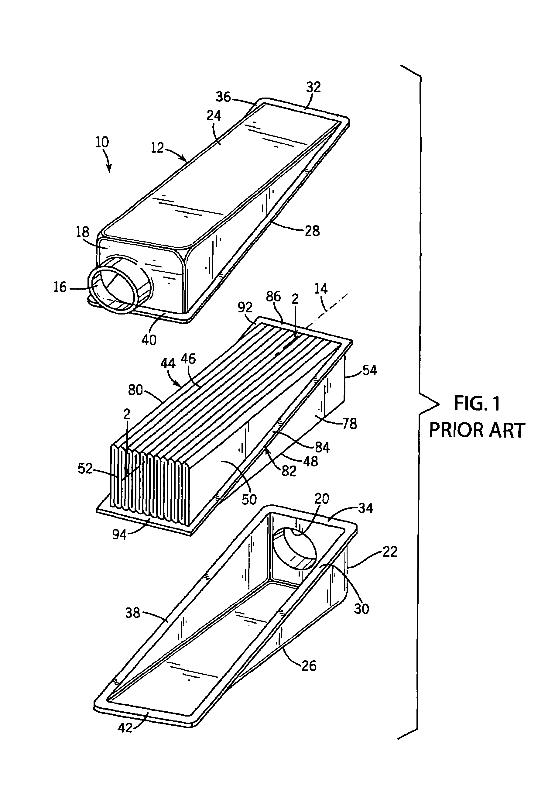
[0018]FIG. 1 shows a filter 10 including a housing 12 extending axially along axis 14 and having an inlet 16 at one axial end 18 of the housing and having an outlet 20 at a distally opposite axial end 22 of the housing. The housing is preferably plastic and provided by identical upper and lower half sections 24 and 26 mating along diagonal flanges 28, 30, lateral flanges 32, 34, diagonal flanges 36, 38, and lateral flanges 40, 42.

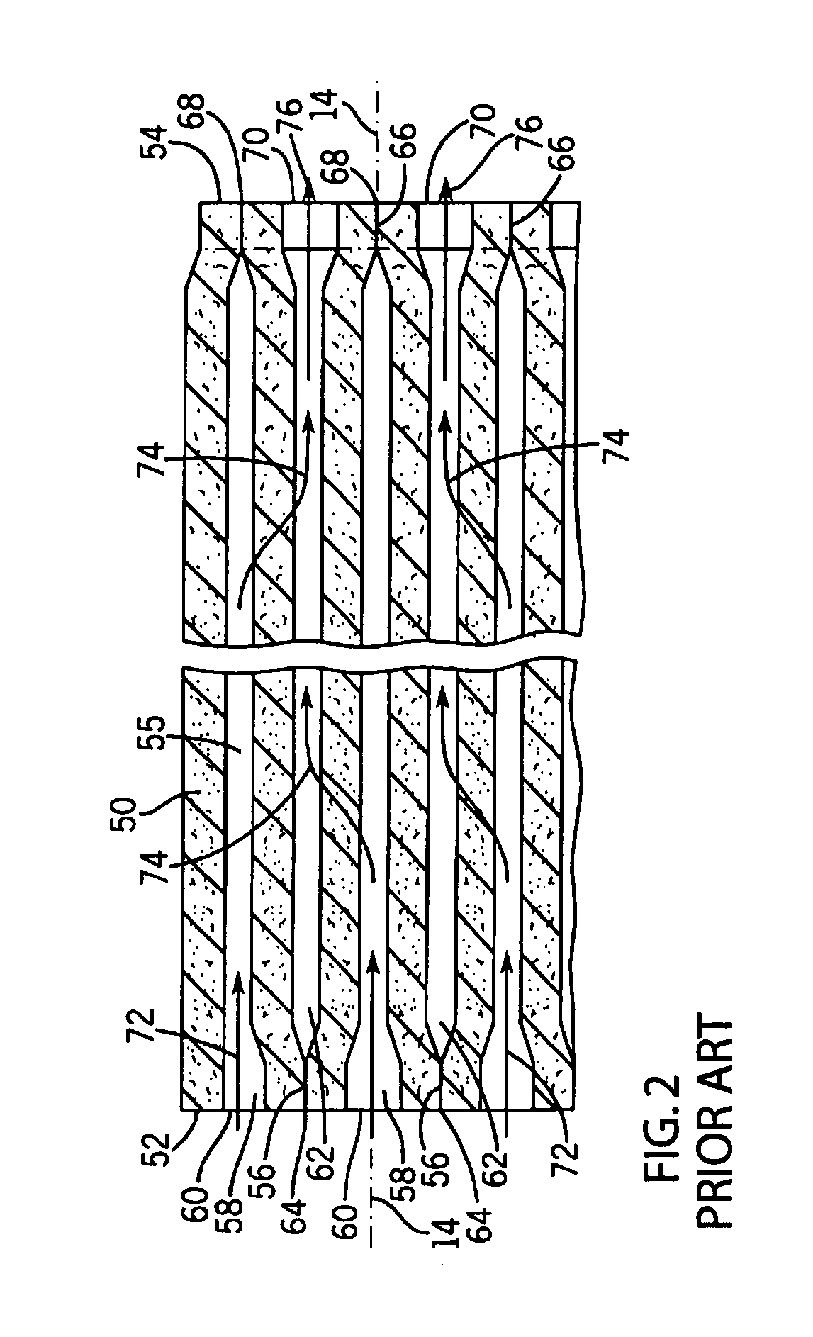
[0019]A pleated filter block is provided by pleated filter element 44 in the housing. The pleated filter element is pleated along a plurality of upper bend lines 46 and lower bend lines 48, which bend lines extend axially. The filter element has a plurality of wall segments 50 extending in serpentine manner between the upper and lower bend lines. The wall segments extend axially between upstream ends 52 at inlet 16, and downstream ends 54 a...


PUM

PropertyMeasurementUnit
widthaaaaaaaaaa
heightaaaaaaaaaa
widthsaaaaaaaaaa

Abstract

A direct flow filter includes a pleated filter element filtering fluid flowing axially therethrough parallel to the wall segment pleat tip bend lines. Embossments on the wall segments have a height extending along a lateral direction into a respective flow channel to maintain channel width and guiding and directing fluid axially into and along the flow channels from the upstream ends of the wall segments.

Description

BACKGROUND AND SUMMARY[0001]The invention relates to fluid filters, and more particularly to direct flow filters.[0002]The invention arose during continuing development efforts relating to direct flow filters. The filtration industry, including for automotive application, is driven towards more efficient space utilization, e.g. eliminating large open areas within a filter element and / or a filter housing between the filter element and the housing, which is particularly desirable in space constrained areas such as behind the cabin or under the hood of vehicles. Direct flow filters are effective for this purpose. A direct flow filter filters fluid flowing along an axial flow direction and includes a pleated filter element having a plurality of pleats defined by wall segments extending along a transverse direction between first and second sets of pleat tips at first and second sets of axially extending bend lines, the transverse direction being perpendicular to the axial direction. In a...

Claims


Application Information

Patent Timeline
Patent Type & Authority Patents(United States)
IPC IPC(8): B01D27/06B01D29/07
CPCB01D46/523
Inventor JANIKOWSKI, ERIC A.DORGAN, JASON E.HOLM, CHRISTOPHER E.LIU, Z. GERALD
Owner CUMMINS FILTRATION INC
Why Eureka
Try Eureka