Method of analyzing injection molding conditions

Inactive Publication Date: 2008-01-29
MITSUBISHI HEAVY IND LTD
View PDF12 Cites 14 Cited by
  • Summary
  • Abstract
  • Description
  • Claims
  • Application Information

AI Technical Summary

Benefits of technology

[0020]According to the present invention, after a user accesses a webpage of a data analysis provider and performs a prescribed application, by inputting simple base data

Problems solved by technology

In this case, if there is a very large amount of molten resin held within the above-noted barrel and pressure is applied, elastic compression occurs, resultin

Method used


Image

  • Method of analyzing injection molding conditions
  • Method of analyzing injection molding conditions
  • Method of analyzing injection molding conditions

Examples


first embodiment

[0040]As the first embodiment, an analysis procedure which takes into consideration the compression ratio of molten resin in the barrel 17 when the inside of the mold 23 is filled with molten resin is described below.

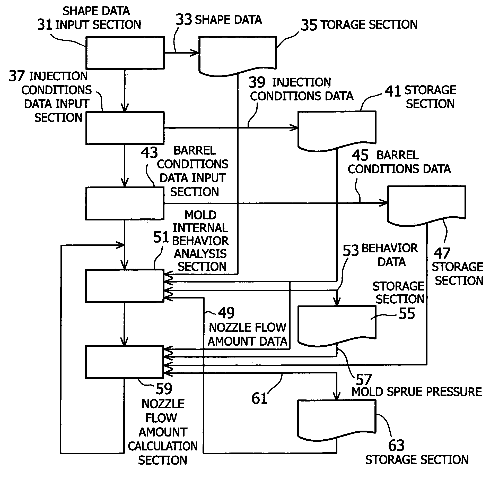
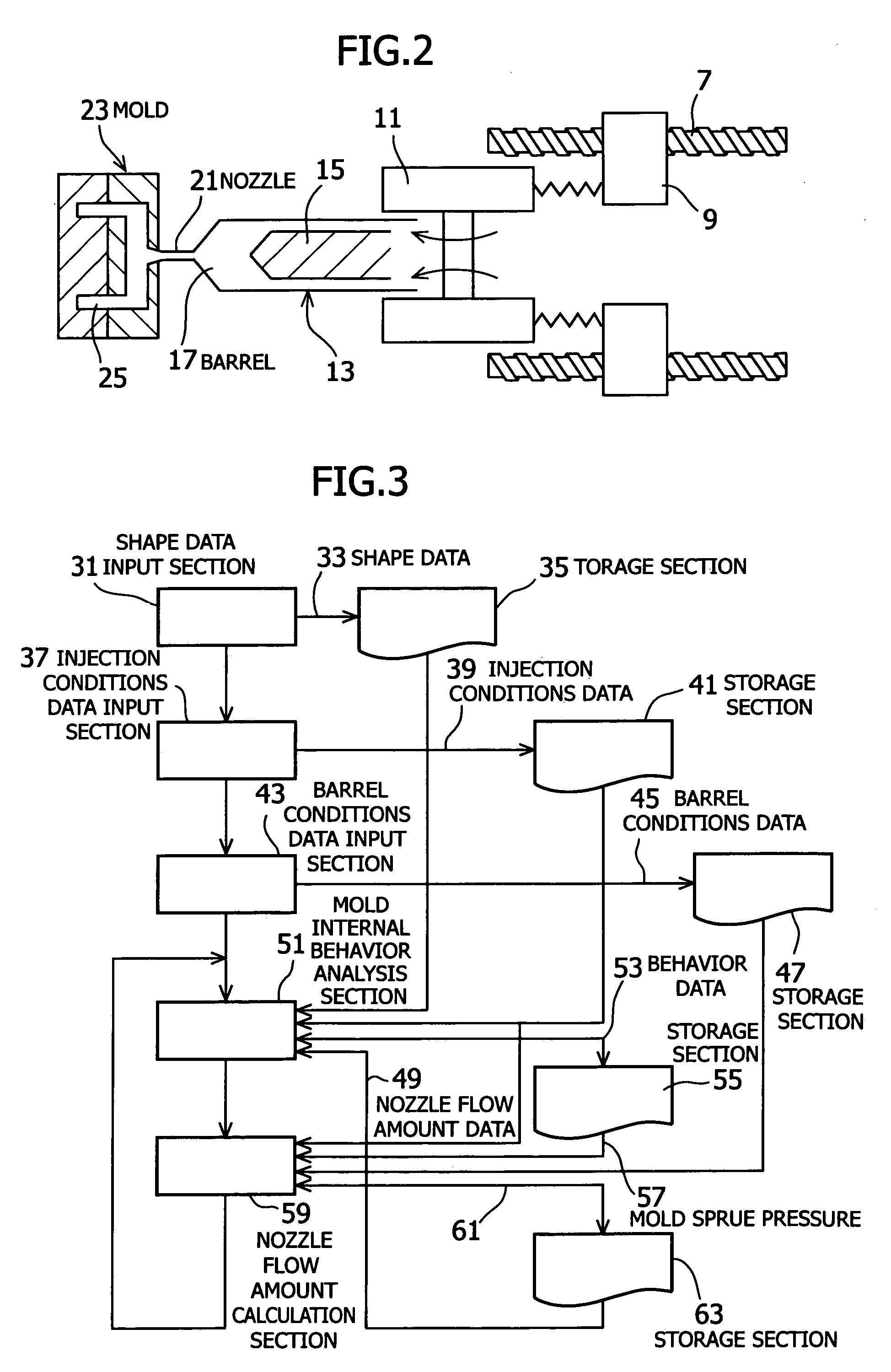
[0041](1) Input of Shape Data

[0042]First, when data regarding the shape of the mold and the shape of the molded resin product (hereinafter referred to as shape data) is input to a shape data input section 31 of a computer, this input shape data 23 is divided into minute elements so as to be usable in numerical analysis methods such as the finite element method, the boundary element method, and the difference method, and stored in the shape data storage section 35.

[0043](2) Input of Injection Condition Data

[0044]Next, when the filling resin physical property data, flow amount and temperature of the filling resin, and time response data of the travel speed of the screw (hereinafter referred to as injection condition data) are input to the injection condition data input se...

second embodiment

[0066]The first embodiment is the case in which analysis is performed of the simultaneous Equations 4 through 8.

[0067]As a second embodiment, an analysis procedure in which, when injecting molten resin in the mold 23 so as to fill the mold, consideration is given to both the compression ratio of molten resin in the barrel 17 and mechanical delays attributed to mechanical constituent elements of the injection molding machine is described below, with reference made to FIG. 4.

[0068](1) Input of Analysis Conditions Data

[0069]First, the target pattern of flow of the filling resin, parameters within the controller, input parameters to the mechanism operation calculation section described below, and shape data (shape of the mold and shape of the resin molded product) are subjected to numerical-processing such as units conversion for suitability to calculations described below, and the shape data is divided into minute elements suitable for a numerical analysis method such as the finite ele...


PUM

PropertyMeasurementUnit
Temperatureaaaaaaaaaa
Pressureaaaaaaaaaa
Speedaaaaaaaaaa

Abstract

A method for analyzing injection molding conditions, which takes into consideration the compressibility of molten resin in a barrel and mechanical delays in resin flow caused by constituent elements of an injection molding machine and analysis results thereof are provided. In a method for analyzing injection molding conditions in which, by using input data having shape data (31) and injection conditions data (37) to perform flow analysis of the process of filling the inside of the mold with molten resin, analysis of the pressure maintenance process from the filling with molten resin to the gate sealing, and analysis of the cooling process within the mold after gate sealing, the pressure and temperature distributions of resin within the mold are calculated, data (43) regarding compressibility of molten resin held in the barrel of the cylinder and mechanical data caused by constituent elements of the injection molding machine are added to the input data.

Description

FIELD OF THE INVENTION[0001]The present invention relates to a method for analyzing the behavior of molten resin that fills a mold when molding a resin product using an injection molding machine, and to a method of providing results of analysis of injection molding conditions via the Internet.BACKGROUND ART[0002]In the past, in the case of molding a product using an injection molding machine, predicted values were determined by simulation, for example by a procedure such as shown in FIG. 8 of the accompanying drawings, and the actual injection of molten resin was done based on these predicted values.[0003]First, when shape data, which is the mold shape and resin object shape is input to the shape data input section 101, this shape data 103 is divided into minute elements so as to be usable in numerical analysis methods such as the finite element method, the boundary element method, and the difference method, and stored in the shape data storage section 105.[0004]Next, when the flow ...

Claims


Application Information

Patent Timeline
IPC IPC(8): B29C45/77G06G7/48B29C45/76B29C45/78
CPCB29C45/7693B29C45/77B29C2945/76056B29C2945/76381B29C2945/76434B29C2945/76993G05B2219/31205G05B2219/45244
Inventor UWAJI, TETSUOAKAZAWA, KIMIOMIZUNO, TAKASHITSUTSUI, KENJIKUWABARA, KOUJI
Owner MITSUBISHI HEAVY IND LTD
Why Eureka
Try Eureka