Discrepancy correction method and apparatus for correcting difference in levels of image signals obtained by an image sensor having a multiple output channels

a technology of image signals and correction methods, applied in the field of discrepancy correction methods and apparatuses for correcting differences in levels of image signals obtained by image sensors, can solve problems such as discrepancy in read signals at the dividing point between the right- and left-side areas, and achieve the effect of reducing signal level differences

Inactive Publication Date: 2008-01-29
CANON KK
View PDF42 Cites 10 Cited by
  • Summary
  • Abstract
  • Description
  • Claims
  • Application Information

AI Technical Summary

Benefits of technology

[0018]The present invention has been made in consideration of the above situation, and has as its object to reduce signal level differences that are a defect of a R / L type sensor used for realizing a high-speed scan operation, and to match linearity between respective output channels.

Problems solved by technology

However, when the R / L type linear sensor as shown in FIG. 26 is used, even slight differences in linearity among the four channels cause differences in level in the output signals separately read for the right- and left-side areas, which results in a discrepancy in read signals at the dividing point between the right- and left-side areas.

Method used


Image

  • Discrepancy correction method and apparatus for correcting difference in levels of image signals obtained by an image sensor having a multiple output channels
  • Discrepancy correction method and apparatus for correcting difference in levels of image signals obtained by an image sensor having a multiple output channels
  • Discrepancy correction method and apparatus for correcting difference in levels of image signals obtained by an image sensor having a multiple output channels

Examples


first embodiment

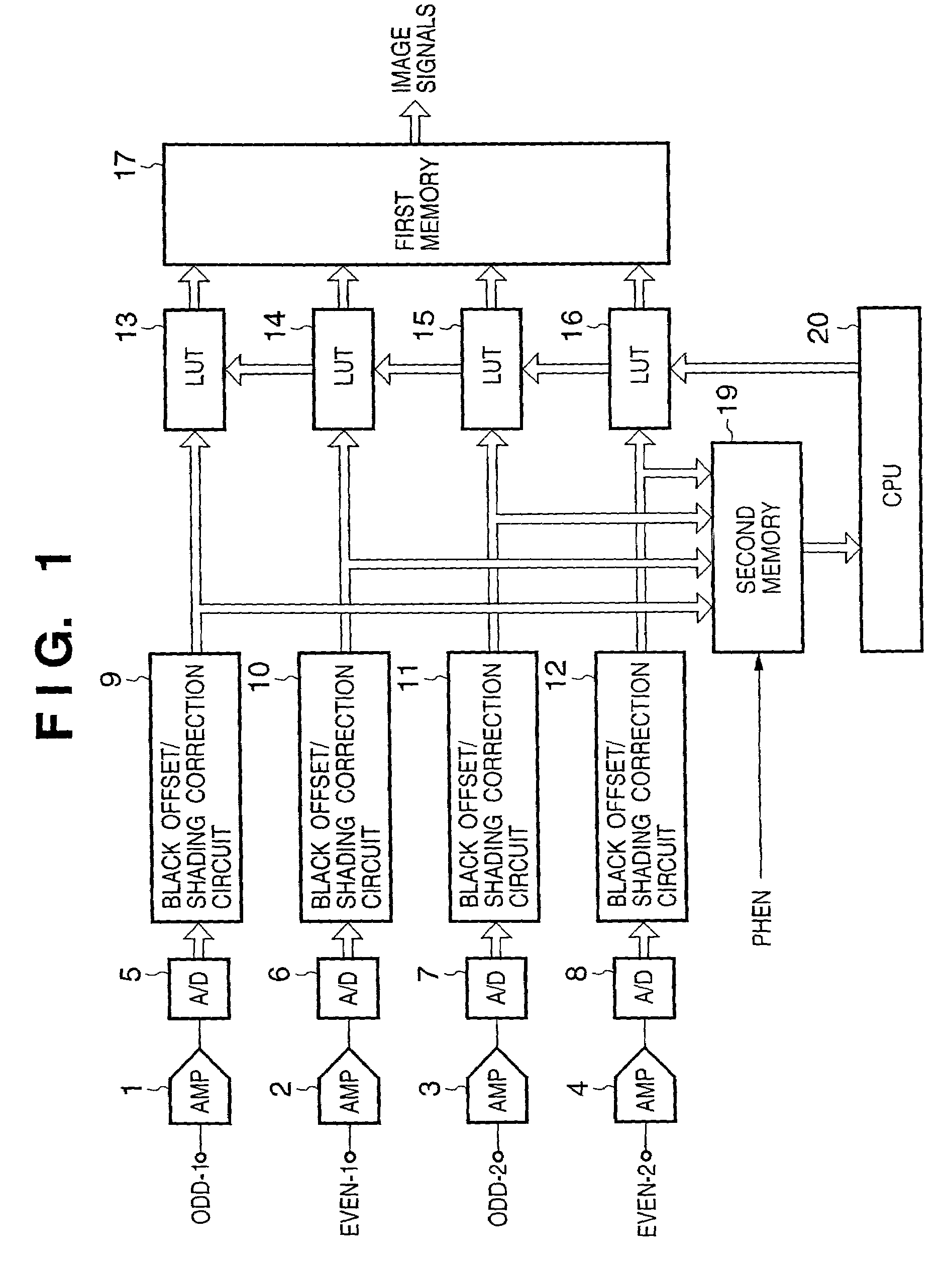
[0053]FIGS. 1 to 3 shows a configuration of an image reading apparatus according to the first embodiment of the present invention.

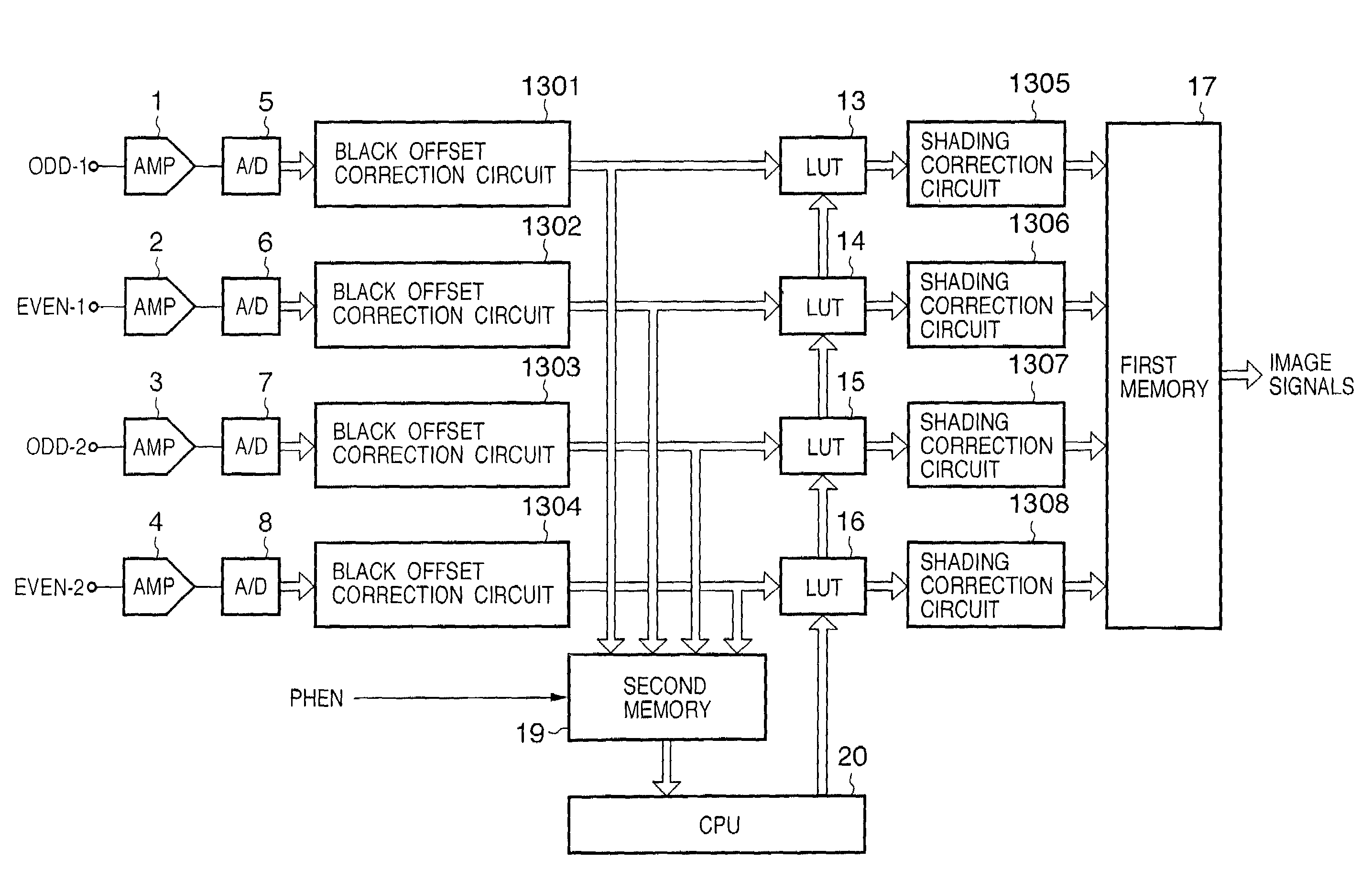
[0054]In FIG. 1, reference numeral 1 to 4 denote amplifiers for amplifying output signals from an R / L type linear sensor as shown in FIG. 26; 5 to 8, A / D converters for converting output signals amplified by the amplifiers 1 to 4 to digital signals; 9 to 12, black offset / shading correction circuits for performing black offset correction by subtracting black offset level from the digital signals and performing shading correction.

[0055]LUTs 13 to 16 as discrepancy correction means are for realizing discrepancy correction (correcting level differences in signals) of the right and left signals by adjusting signal levels of ODD-1, EVEN-1, ODD-2 and EVEN-2.

[0056]A first memory 17 is used for temporarily storing signals output from the R / L type linear sensor at timing shown in FIG. 27, and rearranging the order of the signals to the order of pixels, and outputti...

second embodiment

[0077]Next, the second embodiment will be explained.

[0078]In the first embodiment, the discrepancy correction means are arranged downstream to the shading correction circuits. In other words, signals output from the respective channels are applied with shading correction first, then discrepancy correction next, so that linearity of the signals from the respective channels match. Therefore, when the quantity of light emitted by the illumination lamp changes and gains used in shading correction change, there is a possibility that correction data used in the linearity correction may become inappropriate.

[0079]In order to solve this problem, an image reading apparatus according to the second embodiment of the present invention has a configuration as shown in FIG. 9.

[0080]The configuration shown in FIG. 9 differs from that shown FIG. 1 explained in the first embodiment in that the LUTs 13 to 16 as discrepancy correction means for performing discrepancy correction are arranged upstream to...

third embodiment

[0087]The third embodiment of the present invention will now be explained.

[0088]The configuration of an image reading apparatus according to the third embodiment is the same as that explained in the first embodiment with reference to FIGS. 1 to 3, therefore, the explanation of it is omitted here.

[0089]Next, a method of correcting linearity of the respective channels according to the third embodiment will be explained in detail.

[0090]FIG. 10A shows relationship between signal levels of the respective channels before performing the linearity correction (e.g., LUT conversion). In the graph of FIG. 10A, the abscissa represents brightness of an original, and the ordinate represents signal levels of read image. The black level of each channel is corrected in black level correction, and the white level is corrected in shading correction by the black offset / shading correction circuits 9 to 12. Accordingly, there are not much difference in black and white signal levels between the respective...


PUM


Abstract

Image signals output from a linear image sensor which outputs charges accumulated in pixels in the right-side area and charges accumulated in pixels in the left-side area via different channels are subjected to discrepancy correction. First, a gray reference board is scanned by the linear image sensor while changing charging periods, and look up tables for converting signal levels of the respective channels are generated on the basis of signal levels obtained by scanning the gray reference board. A discrepancy correction is realized by converting levels of image signals output from the two terminals using the look up tables.

Description

FIELD OF THE INVENTION[0001]The present invention relates to an image sensing apparatus utilizing an image sensor having a multiple output channels and a discrepancy correction method for correcting differences in levels of read signals and, more specifically, to an image sensing apparatus, using an image sensor having a multiple output channels, having a discrepancy correction function of correcting differences in levels of signals output via the multiple output channels upon connecting the output signals and a discrepancy correction method for correcting signal level differences in the read signals.BACKGROUND OF THE INVENTION[0002]Conventionally, there is an image reading apparatus using a linear image sensor.[0003]FIG. 24 shows a configuration of a linear CCD image sensor used in a conventional image reading apparatus.[0004]Referring to FIG. 24, reference numeral 101 denotes a photoreceptive pixel array of the linear CCD image sensor; 102 and 103, analog shift registers for seque...

Claims


Application Information

Patent Timeline
Patent Type & Authority Patents(United States)
IPC IPC(8): G06F15/00H04N1/40H04N1/407
CPCH04N1/4076
Inventor OHASHI, KAZUHITO
Owner CANON KK
Why Eureka
Try Eureka