
Power supply apparatus for electric operation

a technology for power supply apparatuses and electric devices, applied in the direction of electric variable regulation, process and machine control, instruments, etc., can solve the problem of slow response speed of power output, and achieve the effect of reducing common-mode nois

Active Publication Date: 2008-01-29
OLYMPUS CORP
View PDF14 Cites 88 Cited by
  • Summary
  • Abstract
  • Description
  • Claims
  • Application Information

AI Technical Summary

Benefits of technology

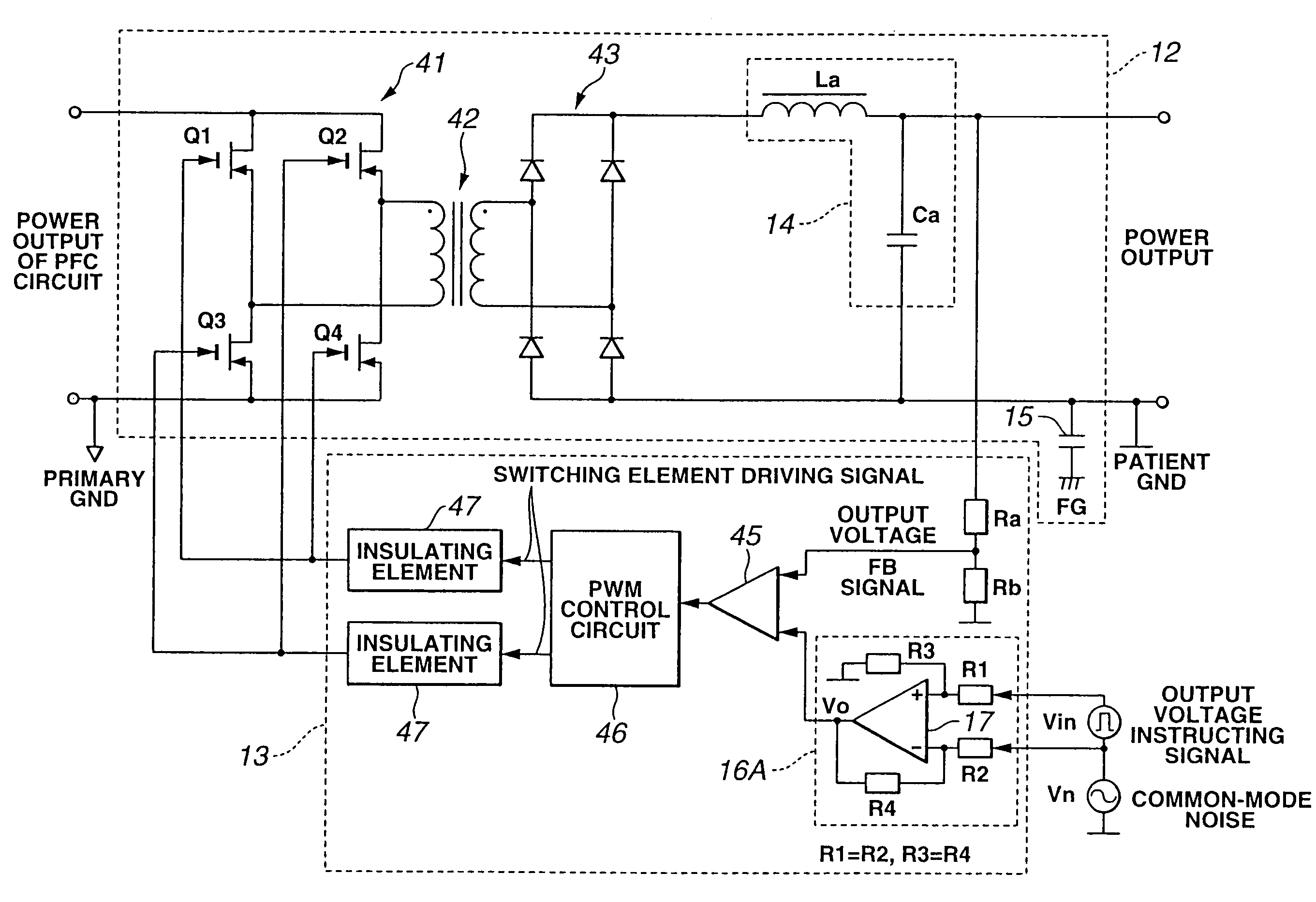
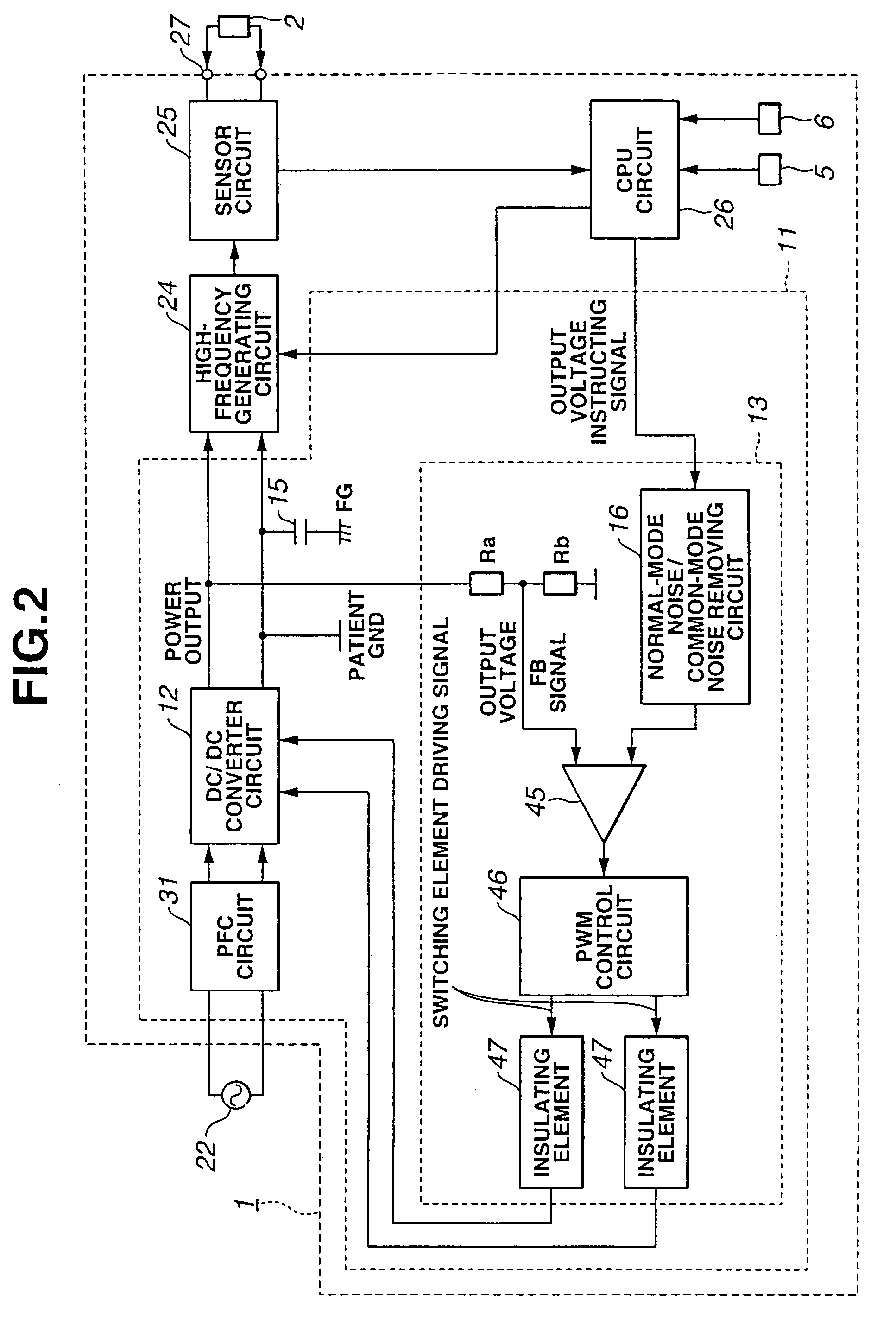
[0031]According to the present invention, a power supply apparatus for electric operation is provided for an electric operation apparatus, and generates a DC output voltage to a high-frequency generating circuit that generates a high frequency. The power supply apparatus for electric operation includes at least a noise reducing circuit which is arranged to a signal input portion that receives an instructing signal for controlling the output voltage and which reduces a common-mode noise.

Problems solved by technology

On the contrary, the response speed of the power output is slow.

Method used


Image

  • Power supply apparatus for electric operation
  • Power supply apparatus for electric operation
  • Power supply apparatus for electric operation

Examples


first embodiment

[0043]the present invention will be described with reference to FIGS. 1 to 4.

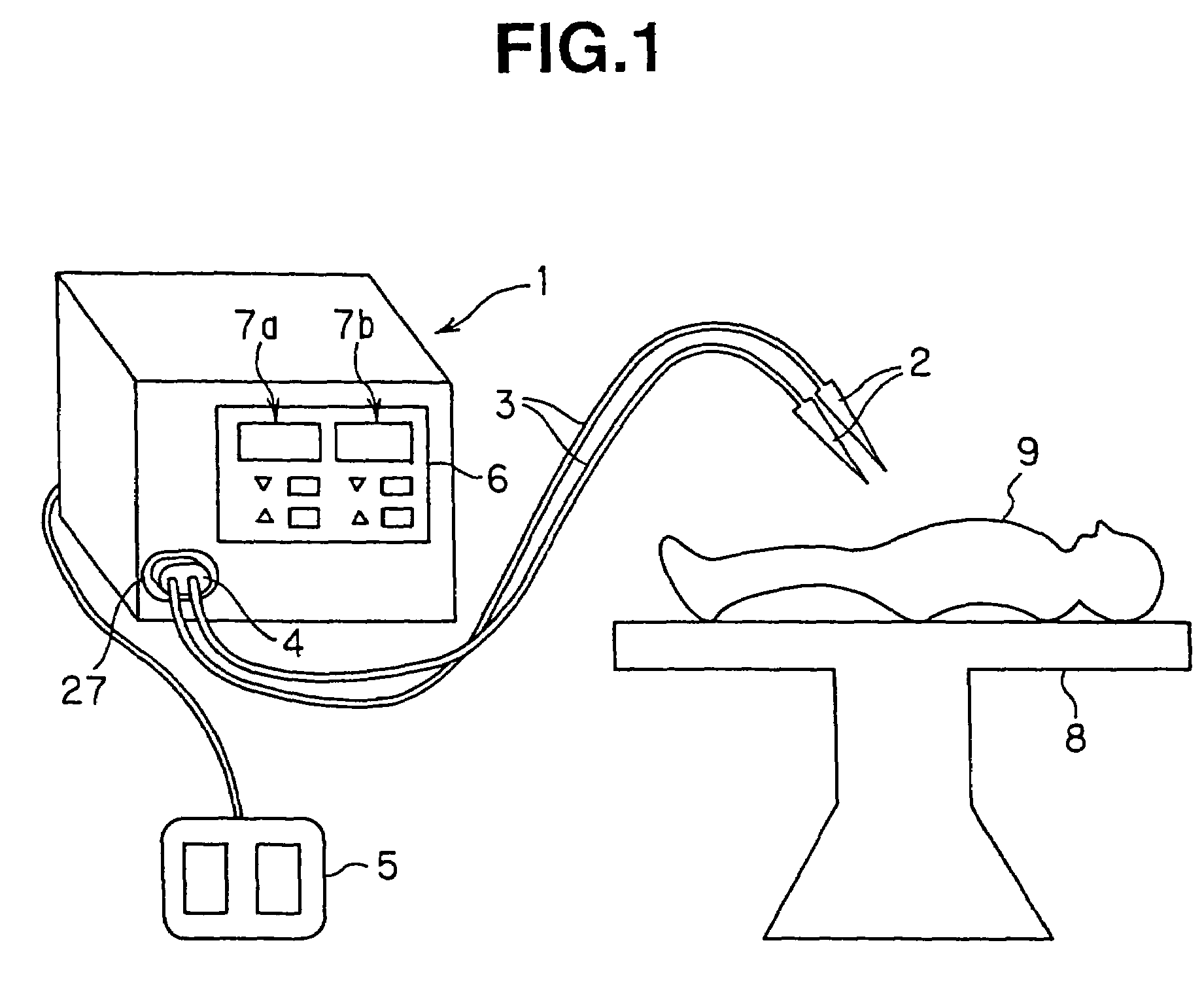
[0044]Referring to FIG. 1, an electric operation apparatus 1 comprises a high-frequency output connector portion 27 in front of a casing. A connector 4 of a cable 3 connected to a high-frequency electric scalpel 2 is detachably connected to the high-frequency output connector portion 27.

[0045]A foot switch 5 is connected to the electric operation apparatus 1, and instructs the on / off operation of the high-frequency output.

[0046]An operating panel 6 of the electric operation apparatus 1 has an incision mode setting portion 7a and a coagulating mode setting portion 7b so as to output the high frequency with an output waveform suitable to the medical treatment such as the incision or coagulation, in accordance therewith, and displays an output setting and an output value in the incision mode setting portion 7a and the coagulating mode setting portion 7b.

[0047]The high-frequency electric scalpel 2 performs a m...

second embodiment

[0093]Next, the present invention will be described with reference to FIG. 5.

[0094]FIG. 5 shows the structure of a main portion of a power supply apparatus according to the second embodiment. According to the second embodiment, an instrumentation amplifier circuit 16B is used as the normal-mode noise / common-mode noise removing circuit 16.

[0095]The non-inverting input terminal of the instrumentation amplifier circuit 16B is connected to the ground of the power output via a resistor R3. The inverting input terminal of the instrumentation amplifier circuit 16B is connected to the output terminal thereof.

[0096]Referring to FIG. 5, reference symbol Vin denotes the output voltage instructing signal and reference symbol vn denotes the common-mode noise. Then, the signals applied to the non-inverting input terminal and inverting input terminal of the instrumentation amplifier circuit 16B are expressed by (Vin+Vn) and Vn, respectively.

[0097]In this case, when R1=R2 and R3=R4, in the instrume...


PUM


Abstract

A power supply apparatus for electric operation is provided for an electric operation apparatus, and includes an instructing signal input portion which generates a DC output voltage to a high-frequency generating circuit that generates a high frequency and which receives an instructing signal for controlling the output voltage. The instructing signal input portion includes at least a noise reducing circuit which reduces a normal-mode noise.

Description

[0001]This application claims benefit of Japanese Application No. 2003-336547 filed on Sep. 26, 2003, the contents of which are incorporated by this reference.BACKGROUND OF THE INVENTION[0002]1. Field of the Invention[0003]The present invention relates to a power supply apparatus for electric operation which is preferably used for an electric operation apparatus.[0004]2. Description of the Related Art[0005]In the surgical or medical operation, an electric operation apparatus is frequently used for treatments for incising or coagulating the affected portion by applying high-frequency current.[0006]FIG. 7 shows the structure of an electric operation apparatus 21 according to a conventional art.[0007]The electric operation apparatus 21 comprises: a power supply apparatus 23 which receives the commercial power supply by its connection to the commercial power supply 22; high-frequency generating circuit 24 which generates a high-frequency output based on a DC power output supplied from t...

Claims


Application Information

Patent Timeline
Patent Type & Authority Patents(United States)
IPC IPC(8): H02M1/12A61B18/12H02M3/337
CPCH02M1/12H02M3/337H02M3/33573
Inventor MIURA, MASAYOSHITAKAHASHI, KAZUMASA
Owner OLYMPUS CORP
Learn More