Layer one switching in a packet, cell, or frame-based network

a network, packet or frame technology, applied in data switching networks, store-and-forward switching systems, multiplex communication, etc., to achieve the effect of ensuring delivery, high degree of accuracy, and maintaining and further tightening timing synchronization

Inactive Publication Date: 2008-01-29
SWXTCH THE RULES
View PDF29 Cites 32 Cited by
  • Summary
  • Abstract
  • Description
  • Claims
  • Application Information

AI Technical Summary

Benefits of technology

[0027]More simply put, all of the store-and-forward device embodiments in the network are synchronized. Then a source or destination sets up a reservation schedule with all of the network devices for transmitting real-time or high-priority packets. At the specific predetermined scheduled time, all of the devices on the scheduled path through the network switch the appropriate input and output lines to bypass their standard store-and-forward switches and switch open a direct non-blocking, non-delaying layer one physical connection from one end of the network to the other. The specific scheduled packets are then transmitted into one end of the network where they propagate directly through all of the layer one switches on the path to the other end of the network, with no delays other than transmission line and layer one switch propagation delays. In this way, they completely bypass the store-and-forward network with all of its inherent disadvantages for continuous, periodic, predictable, time-sensitive, or high-priority information. Once the packets have been sent all the way through the network and the scheduled layer one event is over, the devices switch back to standard store-and-forward switching for bursty, non-periodic, non-predictable, non-time-sensitive, and non-high-priority information. In this way, the system works to optimum advantage and efficiency for each of the two types of data and switching methods.
[0064]It solves the non-guaranteed, random, lossy degraded, and delayed response time problems of packet, cell, and frame-based networks for real-time applications, high-priority messages, and high-quality-of-service.

Problems solved by technology

However, when attempting to deliver continuous, periodic, predictable, time-sensitive, or urgent information, the store-and-forward style architectures are by their nature, ill-suited to efficiently perform the task.
These steps are subject to varying slowdowns and delays based on continuously varying, unpredictable network congestion.
As a result of this dilemma, various complicated schemes have been devised in an attempt to compensate for and circumvent these underlying store-and-forward network characteristics.
The result of these attempts to resolve the problem is a combination of solutions with complicated protocols, complex implementation schemes, and / or inefficient use of network resources.
The explosion of bursty, non-periodic, non-predictable, non-time-sensitive data traffic coupled with converging high-bandwidth, real-time applications over these store-and-forward style packet-, cell-, and frame-based networks inevitably results in network congestion, delays, inconsistent delivery, jitter, packet loss, quality of service degradation, and / or inefficient networks.
With real-time applications and high-priority information, poor network performance resulting in time delays and quality loss can drastically degrade the quality of the end user experience and the value of the service.
Several factors can cause real-time applications such as Internet phone, Internet Video phone, Internet Video Conferencing, Internet Streaming Audio, Internet Streaming Video, and other real-time multimedia applications to suffer in both quality and time delays over packet, cell, or frame-oriented store-and-forward networks.
Among them are:Packet, cell, and frame discard due to a congested switch, which in turn results in dropout glitches (poor quality) and / or increased delay time to retransmit missing packets, cells, or frames.Packet loss due to alternate routing, which in turn results in dropout glitches (poor quality) and increased processing time to recover from and reconstruct missing packets.Waiting for alternate path packets to arrive, resulting in time delays.Reordering of packets that arrive out-of-order, resulting in time delays.Higher layer processing (layers 2-4) of packets at each router before routing the packets on to the next destination, resulting in time delays.Loaded / congested networks which slow down packet, cell, or frame delivery, resulting in random, non-predictable time delays.
However, none of these efforts have been able to completely eliminate a fundamental architectural tenet of packet, cell, and frame-based switching in store-and-forward networks—i.e., when network buffers get overloaded, these systems must drop packets and slow down to “decongest.” This can affect and slow down real-time applications and high-priority information.
However, if the input buffers are full, the real-time application may not be able to get its packet in to be recognized as a high-priority packet.
On the other hand, efforts to overcome this problem by reserving capacity on the switch means the switch will, in effect, limit its input or throughput to reserve capacity for guaranteed applications, thus resulting in inefficiencies in the switch.
However, the large buffers result in long start-time delays for both audio and video “broadcast-style” streaming applications.
Unfortunately, neither of these techniques is sufficient, since network overload and congestion will still cause packet discarding, slowdown, and jitter, enough to cause awkward pauses between end-users.
As mentioned previously, techniques to solve these problems, such as guaranteed constant bit rate or guaranteed peak bit rate, either introduce their own inefficiencies or don't really guarantee the results one hundred percent of the time.
Nevertheless, as more high-bandwidth applications like telephony, web graphics, and streaming video get dumped into these gigabit networks, they too, will either be designed to be inefficient, or will get congested and slow down with the resulting degradation of speed and quality.

Method used


Image

  • Layer one switching in a packet, cell, or frame-based network
  • Layer one switching in a packet, cell, or frame-based network
  • Layer one switching in a packet, cell, or frame-based network

Examples


second embodiment

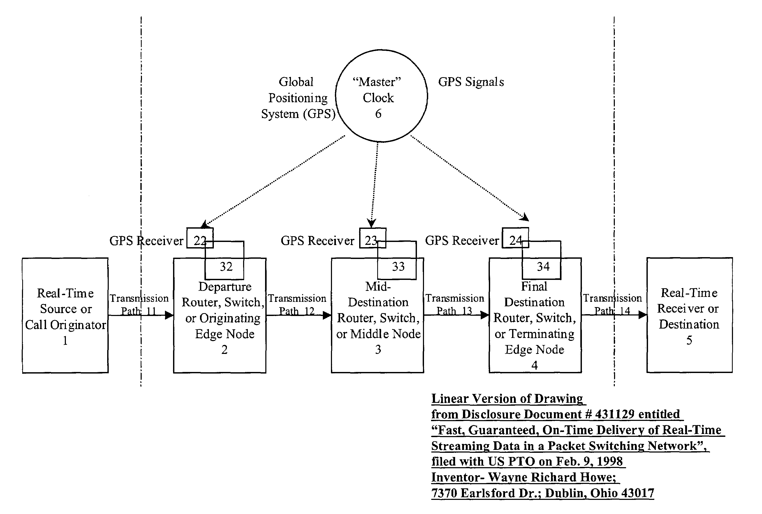
[0146]FIG. 5 is an illustrative example of the layer one network showing the network element devices descriptively entitled an “overlay” embodiment, wherein the packet, cell, or frame routers or switches 2, 3, and 4 are separate devices both structurally and control-wise from the layer one bypass switching systems 32, 33, and 34 respectively. The purpose of this “overlay” embodiment is to be able to less expensively add layer one switching to existing packet networks with existing packet, cell, or frame switches. In this case, only the layer one systems 32, 33, or 34 along with their synchronization means require additional expense.

[0147]In this second embodiment, the layer one controllers in systems 32, 33, and 34 are not the primary controllers of the packet, cell, or frame routers or switches 2, 3, and 4. Packet, cell, or frame routers or switches 2, 3, and 4 can operate as standalone units and control their own functionality. The layer one systems 32, 33, and 34 are “overlaid” o...

seventh embodiment

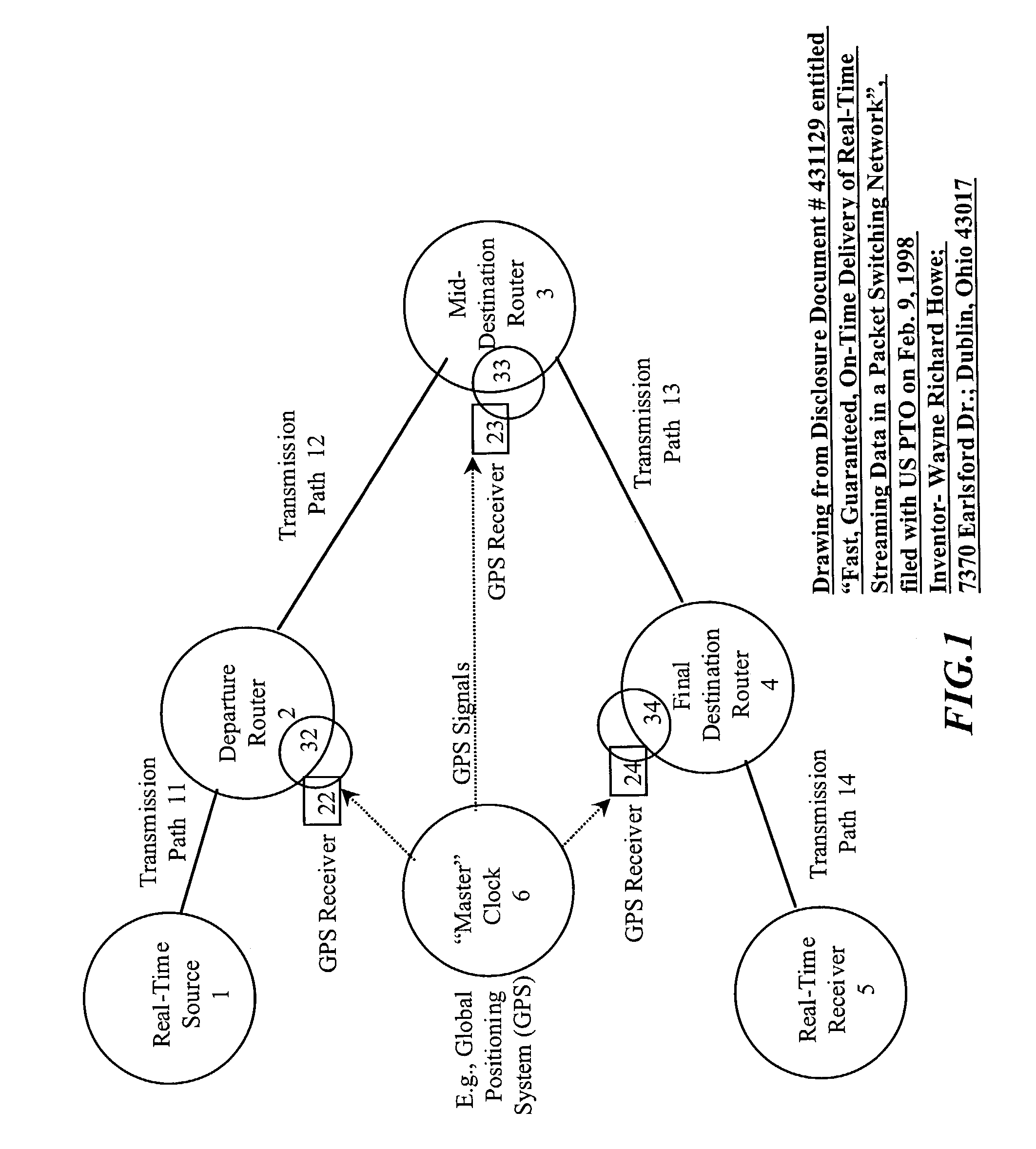
[0152]FIG. 7 is a simplified illustrative example showing elements of a seventh embodiment or “pure layer one” embodiment of the present invention, wherein the standard packet, cell, or frame routers or switches 2, 3, and 4 have been removed entirely, such that the network element “pure layer one” embodiment device consists exclusively of the layer one hardware and software 32, 33, and 34, together with synchronization means 22, 23, and 24. This means that this network performs scheduled layer one switching exclusively, such that standard store-and-forward packet switching does not take place in this embodiment of the present invention. As a result, in FIG. 7, source 1 would request a scheduled time across the layer one network. If the network elements accepted the request, source 1 could transmit its information across the network according to the scheduled times. Source 1 would compete for network resources from other layer one scheduled sessions, but only layer one resources and ...

first embodiment

[0166]FIG. 9 shows a high level block diagram of a first embodiment, also termed the “integrated” embodiment, of an integrated layer one switch. This preferred embodiment integrates a packet, cell, or frame switch 100 into the rest of the layer one switch 32, 33, or 34, comprising a first input switch array 59; an input buffer array 60; a second input switch array 61; a controller 120 with timing synchronization means 22, 23, 24; a non-blocking, non-delaying switch 150; a first output switch array 62, an output buffer array 63, and a second output switch array 69.

[0167]In this preferred embodiment, both layer one packets and standard packets, cells, or frames are routed from the previous node to the input lines such as In1 40. In standard packet mode, while standard packets, cells, or frames are streaming into input line 40, the layer one switch controller 120 uses control line(s) 42 to position switch 41 into the position to route the standard packets, cells, or frames from input l...


PUM


Abstract

A system and method are described for synchronizing store-and-forward networks and for scheduling and transmitting continuous, periodic, predictable, time-sensitive, or urgent information such as real-time and high-priority messages over those networks. This enables packet-, cell-, and / or frame-based networks to thereby efficiently switch voice, video, streaming, and other real-time or high-priority data at the layer one or physical level, thus ensuring that the delivery of selected information can be made fast, on-time, immediate, non-blocked, non-congested, loss-less, jitter-free, and have guaranteed delivery, and guaranteed quality of service.

Description

CROSS-REFERENCE TO RELATED APPLICATIONS[0001]This application is a divisional of U.S. patent application Ser. No. 09 / 375,135, filed on Aug. 16, 1999 now U.S. Pat. No. 6,611,519 and U.S. Provisional Patent Application No. 60 / 097,138, filed Aug. 19, 1998.STATEMENT REGARDING FEDERALLY SPONSORED RESEARCH[0002]Not applicable.FIELD OF THE INVENTION[0003]The present invention relates in general to network communications switching, and more particularly to synchronizing store-and-forward networks and scheduling real-time or high-priority network transmissions for immediate and direct layer one or physical level switching.BACKGROUND OF THE INVENTION[0004]Current applications are consuming network bandwidth at exponentially increasing rates. Current packet-switching, cell-switching, frame-switching, and other store-and-forward communication networks were designed to provide high-efficiency routing and switching capability for bursty, non-periodic, non-predictable, non-time-sensitive data traf...

Claims


Application Information

Patent Timeline
Patent Type & Authority Patents(United States)
IPC IPC(8): H04L12/50H04J3/06H04L12/56
CPCH04L12/5601H04L47/2416H04L49/602H04J3/0638H04J3/0682H04L49/251H04L49/254H04L49/3009H04L49/3018H04L49/3027H04J3/0667H04J3/0644
Inventor HOWE, WAYNE R.
Owner SWXTCH THE RULES
Why Eureka
Try Eureka