System and method for excluding extraneous features from inspection operations performed by a machine vision inspection system

a machine vision inspection and system technology, applied in the field of machine vision inspection systems, can solve the problems of not being easy for machines, difficult to automatically exclude the foreground object or shadow edge from the inspection operation, background object, etc., and achieve the effect of avoiding “tool proliferation” and being easy to use and maintain

Active Publication Date: 2008-01-29
MITUTOYO CORP
View PDF6 Cites 245 Cited by
  • Summary
  • Abstract
  • Description
  • Claims
  • Application Information

AI Technical Summary

Benefits of technology

[0014]One aspect of various embodiments of the invention is that no filtering or other image modifications are performed on the “non-excluded” original image data in the region of the feature to be inspected. Another aspect of various embodiments of the invention is that a region of interest associated with a video tool provided by the user interface of the machine vision system can encompass a region or regions of the feature to be inspected, as well as regions having excluded data, making the video tool easy to use and robust against reasonably expected variations in the spacing between the features to be inspected and the extraneous image features.
[0017]In accordance with another aspect of the invention, a region of interest of a tool can be positioned without consideration of the extraneous image feature (i.e., because the extraneous image feature pixels will be excluded from analysis). That is, the region of interest can span the extraneous image feature and one or more valid edge portions, for example. This greatly simplifies the use of the tool for such applications.
[0019]In accordance with another aspect of the invention, the system performs the extraneous image feature exclusion in a way that allows standard, or near-standard, versions of the various image metrology tools to function for images that include extraneous image features. This results in avoiding “tool proliferation” and the need for related operator training, thus making the overall system easier to use and maintain.

Problems solved by technology

However, these edges are often not features which should be attributed to the background object.
However, it is not so easy for machines.
Since a true background object feature and strong foreground object or shadow edges may be in close proximity in the image, it is difficult to automatically exclude the foreground object or shadow edge from the operations that are trying to measure true features of the background object.

Method used


Image

  • System and method for excluding extraneous features from inspection operations performed by a machine vision inspection system
  • System and method for excluding extraneous features from inspection operations performed by a machine vision inspection system
  • System and method for excluding extraneous features from inspection operations performed by a machine vision inspection system

Examples


Embodiment Construction

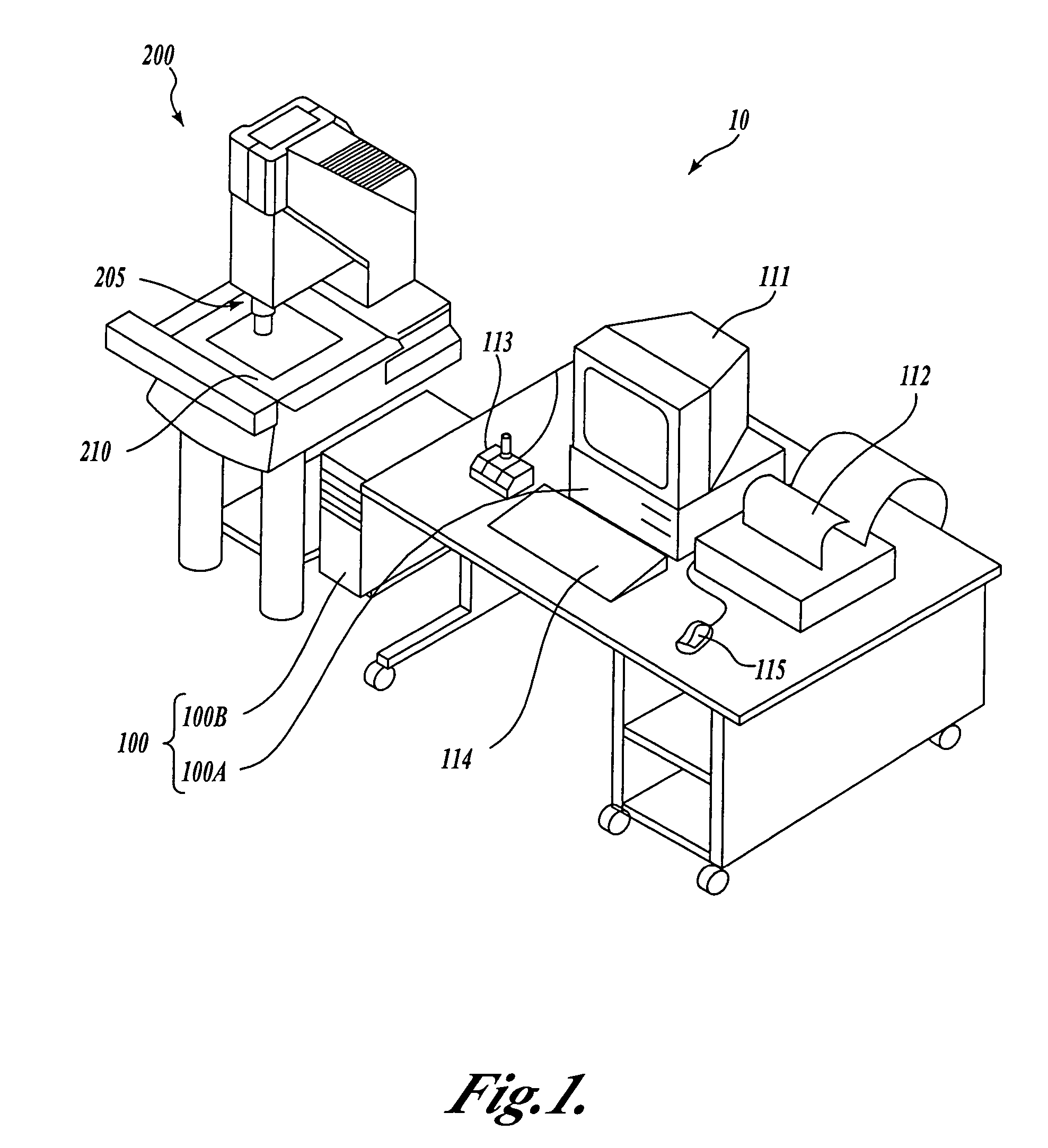
[0040]FIG. 1 is a block diagram of one exemplary embodiment of a general purpose programmable machine vision inspection system 10 in accordance with this invention. The machine vision inspection system 10 includes a vision measuring machine 200 that is operably connected to exchange data and control signals with a control system 100. The control system 100 is further operably connected to exchange data and control signals with one or more of a monitor 111, a printer 112, a joystick 113, a keyboard 114, and / or a mouse 115. The vision measuring machine 200 includes a moveable workpiece stage 210 and an optical imaging system 205 which may include a zoom lens or a number of interchangeable lenses. The zoom lens or interchangeable lenses generally provide various magnifications for the images provided by the optical imaging system 205.

[0041]The joystick 113 can typically be used to control the movement of the movable workpiece stage 210 in both the X and Y directions, which are generall...


PUM

PropertyMeasurementUnit
morphologyaaaaaaaaaa
microscopeaaaaaaaaaa
sizeaaaaaaaaaa

Abstract

Systems and methods are provided for excluding extraneous image features from inspection operations in a machine vision inspection system. The method identifies extraneous features that are close to image features to be inspected. No image modifications are performed on the “non-excluded” image features to be inspected. A video tool region of interest provided by a user interface of the vision system can encompass both the feature to be inspected and the extraneous features, making the video tool easy to use. The extraneous feature excluding operations are concentrated in the region of interest. The user interface for the video tool may operate similarly whether there are extraneous features in the region of interest, or not. The invention is of particular use when inspecting flat panel display screen masks having occluded features that are to be inspected.

Description

FIELD OF THE INVENTION[0001]The invention relates generally to machine vision inspection systems, and more particularly to a system and method for excluding extraneous features from inspection operations.BACKGROUND OF THE INVENTION[0002]Precision machine vision inspection systems can be used to obtain precise dimensional measurements of inspected objects and to inspect various other object characteristics. Such systems may include a computer, a user interface, a lighting system, a camera and optical system, and a precision stage that is movable in multiple directions to allow an operator to position the camera to image various features of a workpiece. The user interface, among other things, generally includes various video tools that are positionable on an inspection image. In this way a user of the machine vision inspection system can position and operate the video tools to perform image processing operations that are useful for various control and inspection operations, while havi...

Claims


Application Information

Patent Timeline
Patent Type & Authority Patents(United States)
IPC IPC(8): G06T5/50G06K9/36G01B11/24G01B11/00G01N21/88G06K9/00G06T1/00G06T5/00G06T7/00
CPCG06T7/0004G06T7/0081G06T7/0091G06T2207/10016G06T2207/20104G06T2207/30164G06T7/11G06T7/155
Inventor WASSERMAN, RICHARD M.
Owner MITUTOYO CORP
Why Eureka
Try Eureka