Image display method, image display apparatus and image display program

a technology of image display and image display, applied in the field of image display method, image display apparatus and image display program, can solve problems such as difficulty in distinguishing between corrections, and achieve the effect of facilitating visual discrimination

Active Publication Date: 2008-01-29
FUJIFILM HLDG CORP +1
View PDF6 Cites 45 Cited by
  • Summary
  • Abstract
  • Description
  • Claims
  • Application Information

AI Technical Summary

Benefits of technology

[0005]In view of the foregoing, a primary object of the present invention is to provide a image display method, a image display apparatus and a image display program, which facilitates visual discrimination between correction results on displayed images which are corrected using different correction parameters.
[0014]Providing at least a referential image display section among these split image display sections makes it possible to compare corrected images with a referential image corrected with default correction parameter values. In order to facilitates the comparison with the referential image, it is preferable to make it possible to change the position of the referential image display section with any of the split image display sections. Then the operator can place the referential image display section in adjacent to an appropriate one of the split image display sections.

Problems solved by technology

Since the above mentioned prior art displays the sample images separately from one another, the operators have to move their eyes widely and repeatedly to compare the sample images to each other, so it is difficult to differentiate between the correction results when the correction parameters are finely adjusted.

Method used


Image

  • Image display method, image display apparatus and image display program
  • Image display method, image display apparatus and image display program
  • Image display method, image display apparatus and image display program

Examples


Embodiment Construction

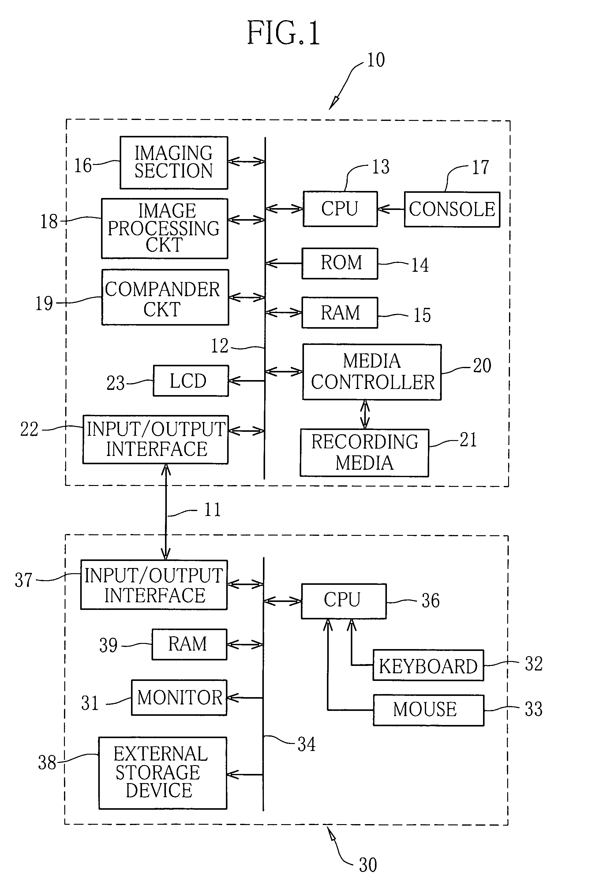
[0026]In FIG. 1, a digital camera 10 and a personal computer (PC) 30 are connected to each other through a communication cable 11, so that they may send and receive camera control data and image data between each other. The image correcting PC 30 may be a commercially available personal computer insofar as it is installed with an image correction program including a image display program of the present invention. The communication cable 11 may be of USB (Universal Serial Bus) type or IEEE1394 type. Instead of the communication cable 11, a radio communication device is usable for data communication between the digital camera 10 and the image correcting PC 30.

[0027]All components of the digital camera 10 are connected to each other through a data bus 12, and their operations are controlled comprehensively by a CPU 13. A ROM 14 stores programs necessary for the operation of the digital camera 10, and some of the programs are loaded in a RAM 15 according to the needs. An imaging section...


PUM


Abstract

An image correcting personal computer displays on its monitor a correction screen consisting of a main display area, a sub display area and a parameter adjusting area. The main display area is divided into a plural number of split image display sections displaying split images corresponding to the same fragment of an image to correct. The split image display sections may display the split images in conditions corrected differently from each other, by changing the correction parameters on the parameter adjusting area while selecting one of the split image display sections, except a referential display section that displays the split image in default conditions corrected with fixed correction parameter values.

Description

FIELD OF THE INVENTION[0001]The present invention relates to a method of and an apparatus for displaying images on a monitor that is attached to a data processing terminal such as a personal computer, for processing electronic or digital images taken through a digital camera and the like. The present invention relates also to a image display program for these method and apparatus.BACKGROUND ARTS[0002]With a personal computer or other kind of data processing terminal, digital images can be corrected in color-balance, tone curve or other characteristics, to improve their qualities. For example, image data taken through a digital camera are sent to the personal computer. Then, an operator may adjusts various kinds of correction parameters while observing images displayed on a monitor of the personal computer based on the image data, in order to finish images according to the operator's intension. In case of a digital camera that can output original or raw image data that is not subject...

Claims


Application Information

Patent Timeline
Patent Type & Authority Patents(United States)
IPC IPC(8): G03B29/00G06F17/00G06K15/02H04N1/60G06T11/60G06T1/00G06T5/00G09G5/00G09G5/02G09G5/14H04N1/387H04N1/407H04N1/46
CPCH04N1/6011H04N1/6013
Inventor KUBO, MASAHIRO
Owner FUJIFILM HLDG CORP
Why Eureka
Try Eureka