Automotive air conditioning system

a technology for air conditioning systems and automobiles, applied in the direction of temperatue control, process and machine control, instruments, etc., can solve the problems of reducing the comfort level provided during bilevel mode operation, unable to establish the temperature distribution of foot-warm outlet, and prolonging the operating time of the engine, so as to improve fuel economy and comfort. , the effect of improving the comfor

Inactive Publication Date: 2008-02-05
DENSO CORP
View PDF7 Cites 24 Cited by
  • Summary
  • Abstract
  • Description
  • Claims
  • Application Information

AI Technical Summary

Benefits of technology

[0012]The invention was made in view of these situations and an object thereof is to provide an automotive air conditioning system which can make the improvement in comfort during a bilevel mode operation compatible with the improvement in fuel economy during a foot mode operation.
[0022]According to the construction, as the foot outlet temperature can be increased higher during the bilevel mode operation than during the foot mode operation, the face outlet temperature can be decreased lower than the foot outlet temperature by that amount to thereby establish the face-cool, foot-warm temperature distribution. Consequently, the comfort during the bilevel mode operation can be improved.
[0024]Furthermore, it is only when the bilevel mode operation is implemented that the heating capacity of the heater (51, 49) is increased, and during the foot mode operation, the heater (51, 49) only has to be controlled so as to provide a required minimum heating capacity that corresponds to the target air-outlet temperature (TAO). Consequently, energy saving can be attained during the foot mode operation.
[0025]Thus, the attainment of energy saving during the foot mode operation and the improvement in comfort during the bilevel mode operation can be made compatible with each other.

Problems solved by technology

Moreover, as the set coolant temperature is the minimum coolant temperature required to obtain the target air-outlet temperature TAO, the face-cool, foot-warm outlet temperature distribution cannot be established when the bilevel mode is used for the following reason.
As a result, in reality, during a bilevel mode operation, air delivered from the foot outlet and air delivered from the face outlet are delivered at the same temperature, that is, the target air-outlet temperature TAO, and this lowers the comfort level provided during the bilevel mode operation.
This leads to a longer operating time of the engine and worsens the fuel economy thereof, and eventually, the advantage inherent in hybrid vehicles is lost.

Method used


Image

  • Automotive air conditioning system
  • Automotive air conditioning system
  • Automotive air conditioning system

Examples


first embodiment

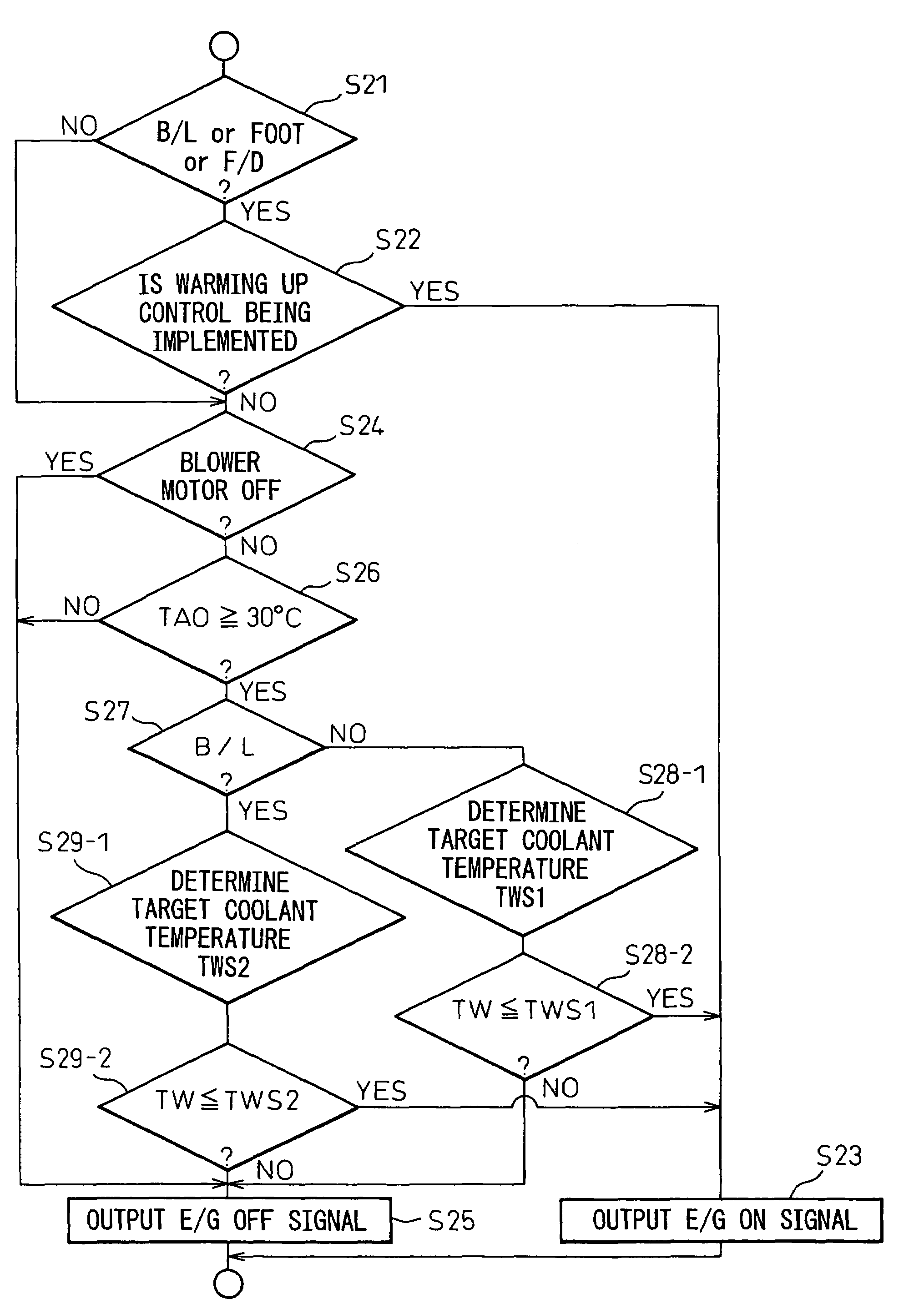
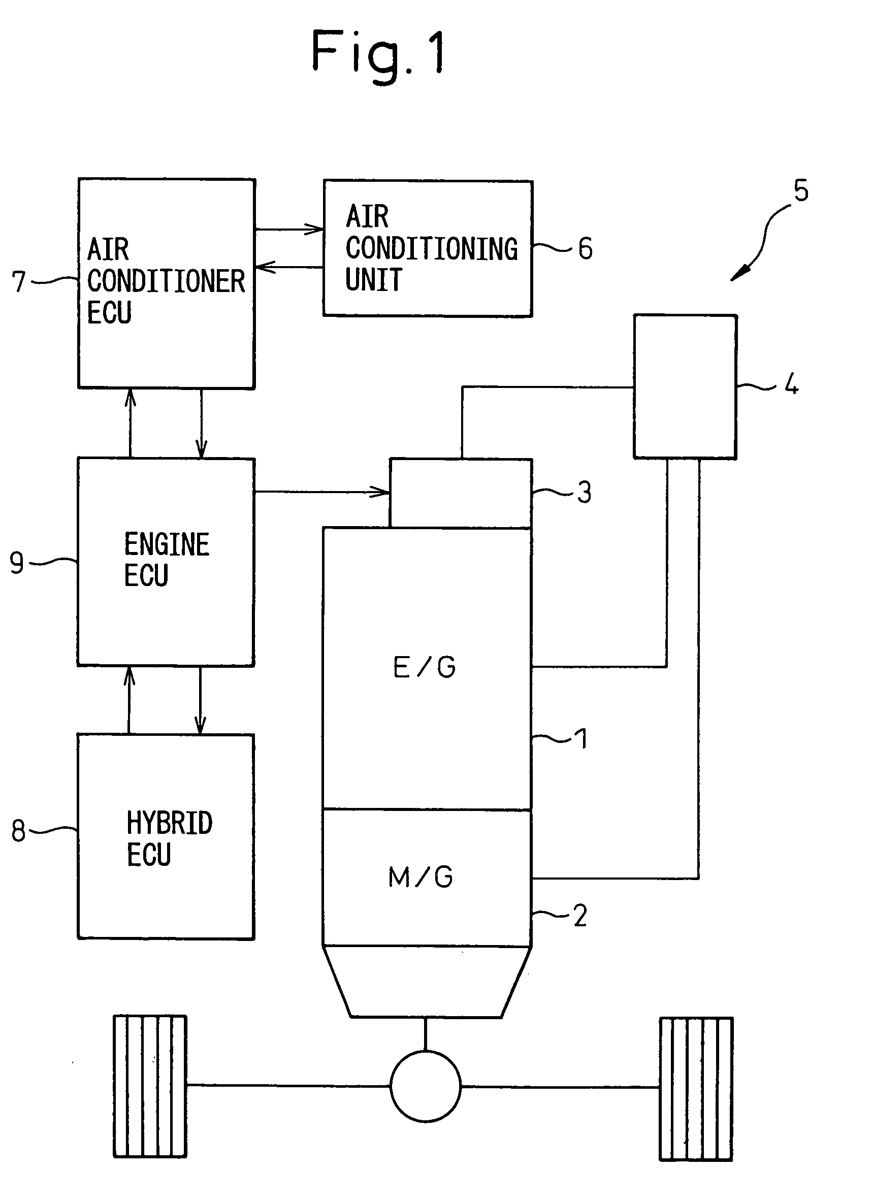
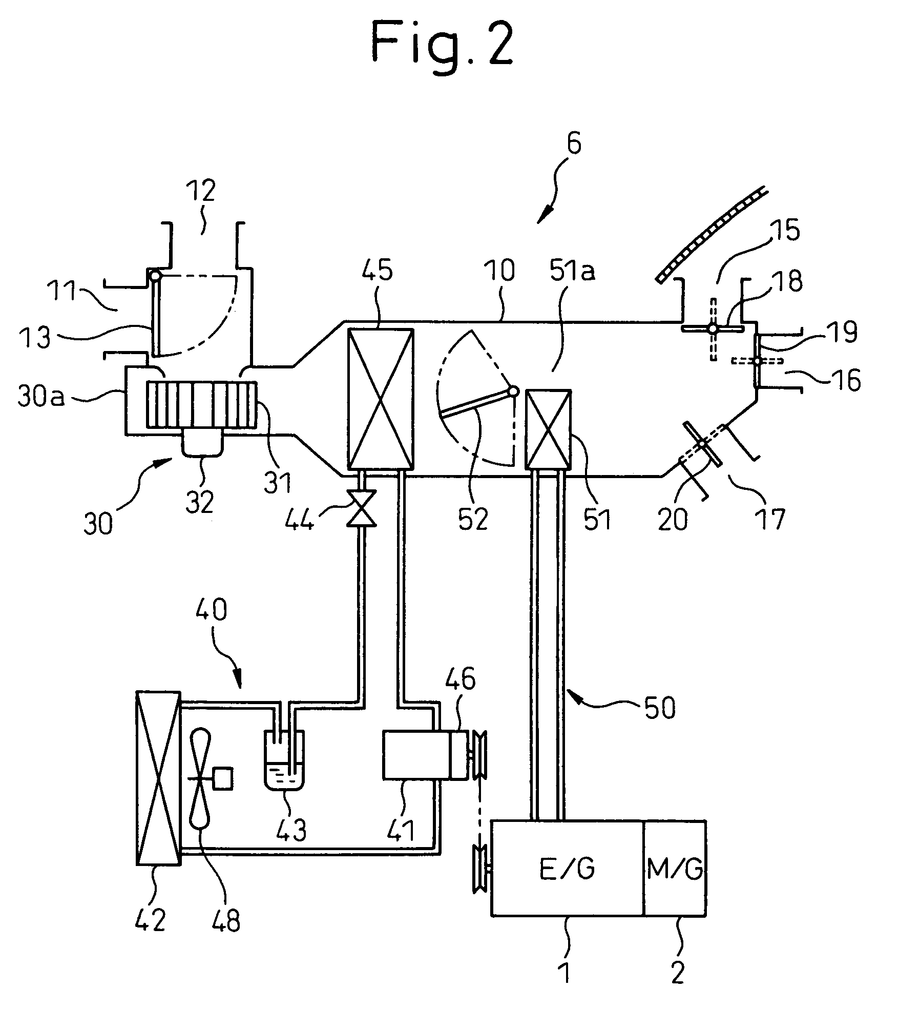
[0063]FIGS. 1 to 13 illustrate a first embodiment in which the invention is applied to a hybrid-vehicle air conditioning system. FIG. 1 illustrates schematically the construction of a driving mechanism for running of a hybrid vehicle, FIG. 2 shows an overall construction of a hybrid-vehicle air conditioning system, and FIG. 3 illustrates a control system of the hybrid-vehicle air conditioning system.

[0064]As shown in FIG. 1, a vehicle running water-cooled gasoline engine (hereinafter, referred to as the vehicle running engine) 1, a vehicle running motor 2 made up of an electric generator, an engine starting system 3 including a starter motor for starting the vehicle running engine 1, an ignition system and a fuel injection system and a battery 4 (a nickel hydrogen battery) 4 for supplying power to the vehicle running motor 2 and the engine starting system 3 are installed on a hybrid vehicle (a hybrid automobile) 5 according the embodiment.

[0065]Note that the vehicle running engine 1...

second embodiment

[0135]While, in the first embodiment, the heater core 51 for heating air using the engine coolant supplied from the vehicle running engine 1 as the heat source is used as the heater for heating air sent out into the passenger compartment, a heater for heating air that is sent out into the passenger compartment is made up of a radiator on a high-pressure side of the refrigeration cycle in a second embodiment.

[0136]The second embodiment will be described by reference to FIG. 14. FIG. 14 shows an air conditioning system that is applied to an electric vehicle which is provided with a vehicle running motor as a driving source for running the vehicle and with no vehicle running engine. Here, the electric vehicle may be a type such as a fuel cell vehicle in which a vehicle running motor and an on-board battery are charged with fuel cells and an electric vehicle in which an on-board battery is charged with a battery charger outside the vehicle.

[0137]In a refrigeration cycle 40, a compressor...

third embodiment

[0149]While, in the first embodiment, the engine coolant that is heated by the vehicle running engine 1 is used as hot water that circulates to the heater core 51 for heating air that is sent out into the passenger compartment, in a third embodiment, as shown in FIG. 15, hot water that is circulated to a heater core 51 is designed to be heated by an electric heater 86.

[0150]As with the second embodiment, the third embodiment is also directed to an electric vehicle which is provided with no vehicle running engine. Consequently, a compressor 41 in a refrigeration cycle 40 is an electric compressor that is driven by an electric motor energized by an on-board battery. The remaining features of the third embodiment are identical to those of the first embodiment.

[0151]In the third embodiment, by adjusting the heating capacity of the electric heater 86, the temperature of hot water that is circulated to a heater core 51 can be adjusted. Consequently, also in the third embodiment, similar f...


PUM


Abstract

In a hybrid vehicle air conditioning system in which coolant is supplied to a heater core from a vehicle running engine, for heating, a demand of the operation of the vehicle running engine is controlled to obtain respective set coolant temperatures TWS2 for target air-outlet temperature TAO of air sent out into a passenger compartment during a bilevel mode operation and TWS1 for the target air-outlet temperature TAO during a foot mode operation by setting the set coolant temperature TWS2 higher than the set coolant temperature TWS1.

Description

BACKGROUND OF THE INVENTION[0001]1. Technical Field of the Invention[0002]The present invention relates to control of the heating capability of a passenger compartment heater, in an automotive air conditioning system, which can preferably be applied to hybrid vehicles.[0003]2. Description of the Related Art[0004]Conventionally, there are descriptions of engine operation controls to secure a required minimum coolant temperature for a heating function in automotive air conditioning systems that are applied to hybrid vehicles in which a vehicle running engine and a vehicle running motor are installed, and Japanese Patent Publication No. 3323097 describes one of the conventional examples.[0005]In this related art, when a target air-outlet temperature TAO, for air blown out into the passenger compartment, is equal to or higher than a predetermined temperature (for example, 30° C.) and the temperature of an engine coolant, which is a heating medium for heating, is equal to or lower than a...

Claims


Application Information

Patent Timeline
Patent Type & Authority Patents(United States)
IPC IPC(8): B60H1/00B60H1/08B60H1/22
CPCB60H1/004B60H1/00921Y02T10/88
Inventor HOMAN, TOSHINOBUOOMURA, MITSUYOYOSHIDA, MAKOTO
Owner DENSO CORP
Why Eureka
Try Eureka