Electrically operated drive-in tool

a drive-in tool and electric motor technology, which is applied in the direction of manufacturing tools, nailing tools, tapering tools, etc., can solve the problems of high cost, high cost, and low practicality of the return wheel switch mechanism, and achieve reliable return of the driving ram, high driving energy, and adequate useful life

Inactive Publication Date: 2008-02-05
HILTI AG
View PDF20 Cites 16 Cited by
  • Summary
  • Abstract
  • Description
  • Claims
  • Application Information

AI Technical Summary

Benefits of technology

[0010]It is the object of the present invention to develop a drive-in tool of the type mentioned above which insures a reliable return of the driving ram at higher driving energies, greater than 35 J, and which has an adequate useful life.
[0011]This and other objects of the present invention, which will become apparent hereinafter, are achieved by providing a return device having a return motor which is connected with the driving ram by a return mechanism. This return motor which is not dependent on the electric motor of the drive unit enables a flexible control of the ram return. Further, the return mechanism can slip or disengage during the drive-in process so that there is no loss of energy as there is with a return spring. Further, the return device according to the invention has a longer life and is less prone to malfunction. The return motor can be formed as a rotary motor or as a linear motor.
[0012]It is advantageous when the return motor has an output in the range of 0.1% to 20% of the output of the electric motor that drives the flywheel. Typical electric drive motors for drive-in tools have a power requirement of about 150 W to 400 W. Due to its relatively low power consumption, the return motor has sufficient energy available because its power consumption is practically negligible compared to that of the flywheel drive motor. Further, in view of its low power consumption, the return motor can be an inexpensive small motor so that the production costs for the drive-in tool can be kept low.
[0014]Further, it is advantageous when the return device has at least one switching mechanism for detecting an end position of the driving ram opposite the starting position. The return device can be put into operation in a simple manner by this switching mechanism when the driving ram is in its end position at the end of a drive-in process.
[0015]Further, it is advantageous when the return device has at least one further switching mechanism for detecting the initial position of the driving ram. In this way, the return device can be switched off in a simple manner when the driving ram has been moved by the return device to its initial position again. If a second switching mechanism of this kind is not provided, the return device can also be switched off in a time-controlled manner, for example.
[0017]It is also advantageous when the return mechanism is formed as a return roller or as a friction wheel. This friction wheel can be freewheeling in the driving direction of the piston in order to prevent energy losses in the driving ram during the setting process. A friction wheel is economical and is well suited for transmitting the necessary return forces to the driving ram.

Problems solved by technology

However, returning the driving ram with a flexible belt is only practical in drive-in tools with low setting power.
This is disadvantageous in that the mechanism for switching the return wheel is very complicated and slow.
The drawback of the device of this U.S. Patent consists that the mechanical return spring does not have the required useful life in drive-in tools with a setting power greater than about 35 J. Further, the mass of the spring leads to drastic energy losses.

Method used


Image

  • Electrically operated drive-in tool
  • Electrically operated drive-in tool
  • Electrically operated drive-in tool

Examples


Embodiment Construction

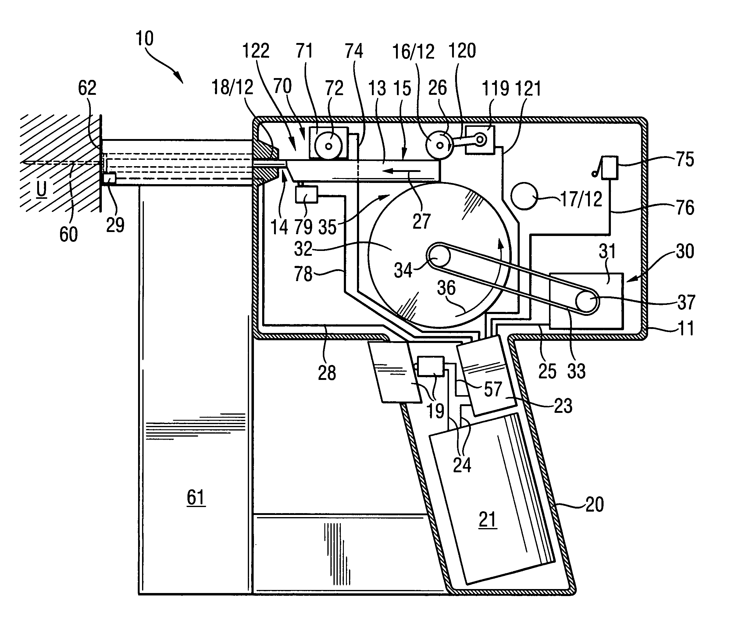
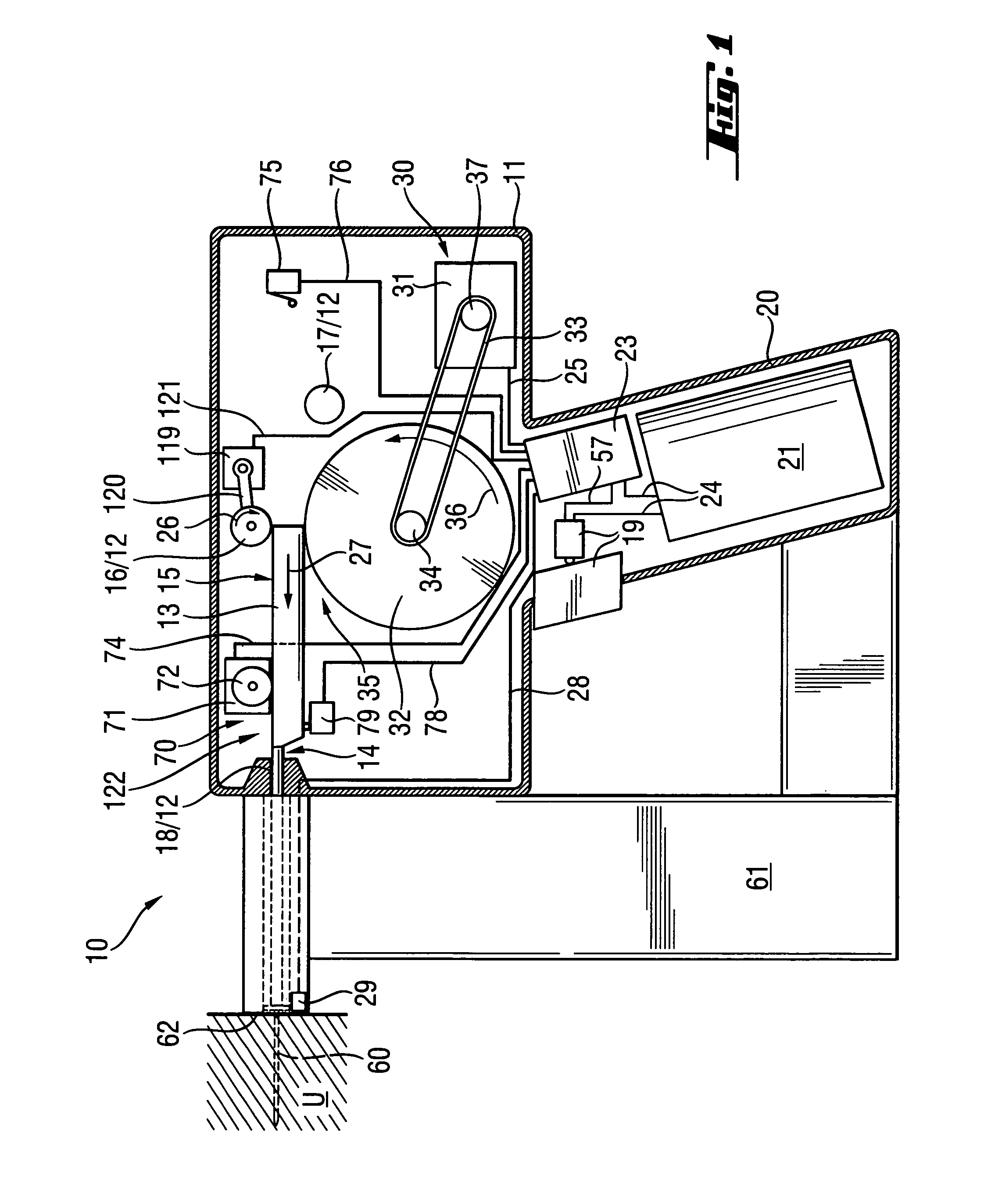
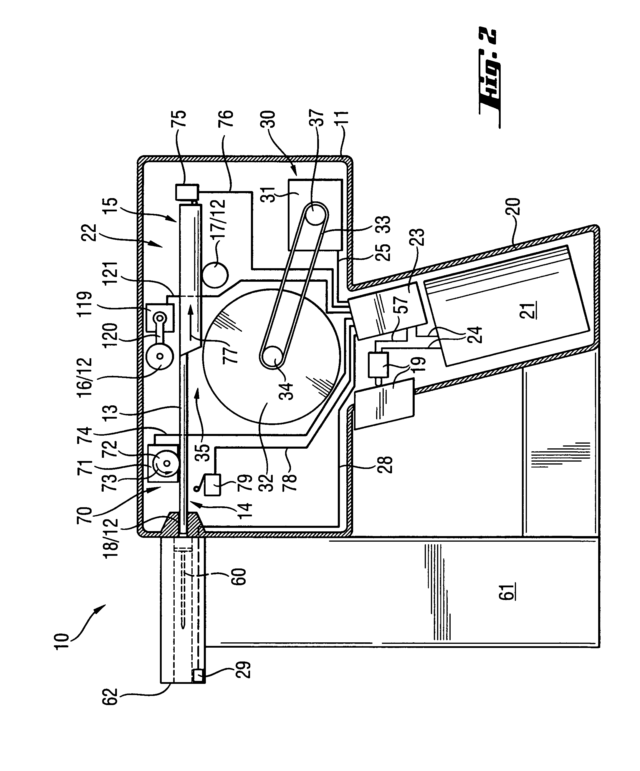
[0022]The drive-in tool 10, which is shown in FIGS. 1 and 2, has a housing 11 and a drive unit, designated in its entirety with a reference numeral 30 and which is arranged in the housing 11 for driving a driving ram 13 which displaceable in a guide 12. The guide 12 has a guide roller 17, contact pressing means 16 which is formed as a contact pressing roller, and a guide channel 18. A fastening element magazine 61, in which fastening elements 60 are loaded, is arranged at the end of the guide 12 in the driving direction 27 so as to project laterally therefrom.

[0023]Further, the drive-in tool 10 has a handle 20 on which a trigger switch 19 is arranged for triggering a drive-in process with the drive-in tool 10. A power supply, designated in its entirety by 21, is arranged in the handle 20 and supplies the drive-in tool 10 with electrical energy. The power supply 21 has at least one battery in the present case. The power supply 21 is connected to a control unit 23 and to the trigger s...


PUM


Abstract

A drive-in tool drives in fastening elements and includes a driving ram and a drive unit. The driving ram is displaceably supported in a guide. The drive unit has a drive flywheel and a return device. The drive flywheel is set in rotation by an electric motor, and the return device displaces the driving ram from an initial position after the completion of the drive-in process. The return device has a return motor separate from the electric motor, and the return motor is connected to the driving ram by a return mechanism.

Description

BACKGROUND OF THE INVENTION[0001]1. Field of the Invention[0002]The invention is directed to an electrically operated drive-in tool having a ram for driving in a fastening element and supported in a guide for displacement therein, a drive unit for driving the ram and having at least one flywheel driven by an electric motor, and a return device for returning the ram in its initial position upon completion of the drive-in process. In drive-in tools of this type, fastening elements are driven into a substrate by a driving movement of the driving ram.[0003]2. Description of the Prior Art[0004]In the electrically operated drive-in tools, the driving ram is accelerated by at least one flywheel which can be driven by an electric motor. In drive-in tools which draw their energy from a battery, the driving energy is approximately 35 J to 40 J. According to the flywheel principle realized in the drive-in tools, the energy stored in the flywheel is transmitted to the driving ram by a clutch. T...

Claims


Application Information

Patent Timeline
Patent Type & Authority Patents(United States)
IPC IPC(8): B25C5/06
CPCB25C1/06
Inventor SCHIESTL, ULRICHSTAUSS, PETER
Owner HILTI AG
Why Eureka
Try Eureka