
Electronic module of electric connector

Inactive Publication Date: 2008-02-05
SPEED TECH
View PDF11 Cites 35 Cited by
  • Summary
  • Abstract
  • Description
  • Claims
  • Application Information

AI Technical Summary

Benefits of technology

[0008]Accordingly, the present invention provides an electronic module of an electric connector, which is suitable for mass production, can avoid pulling apart the conductive leads, and solve the problem that the terminals cannot firmly clamp the conductive leads. Additionally, the present invention simplifies the step of removing the insulative layers of the conductive leads.
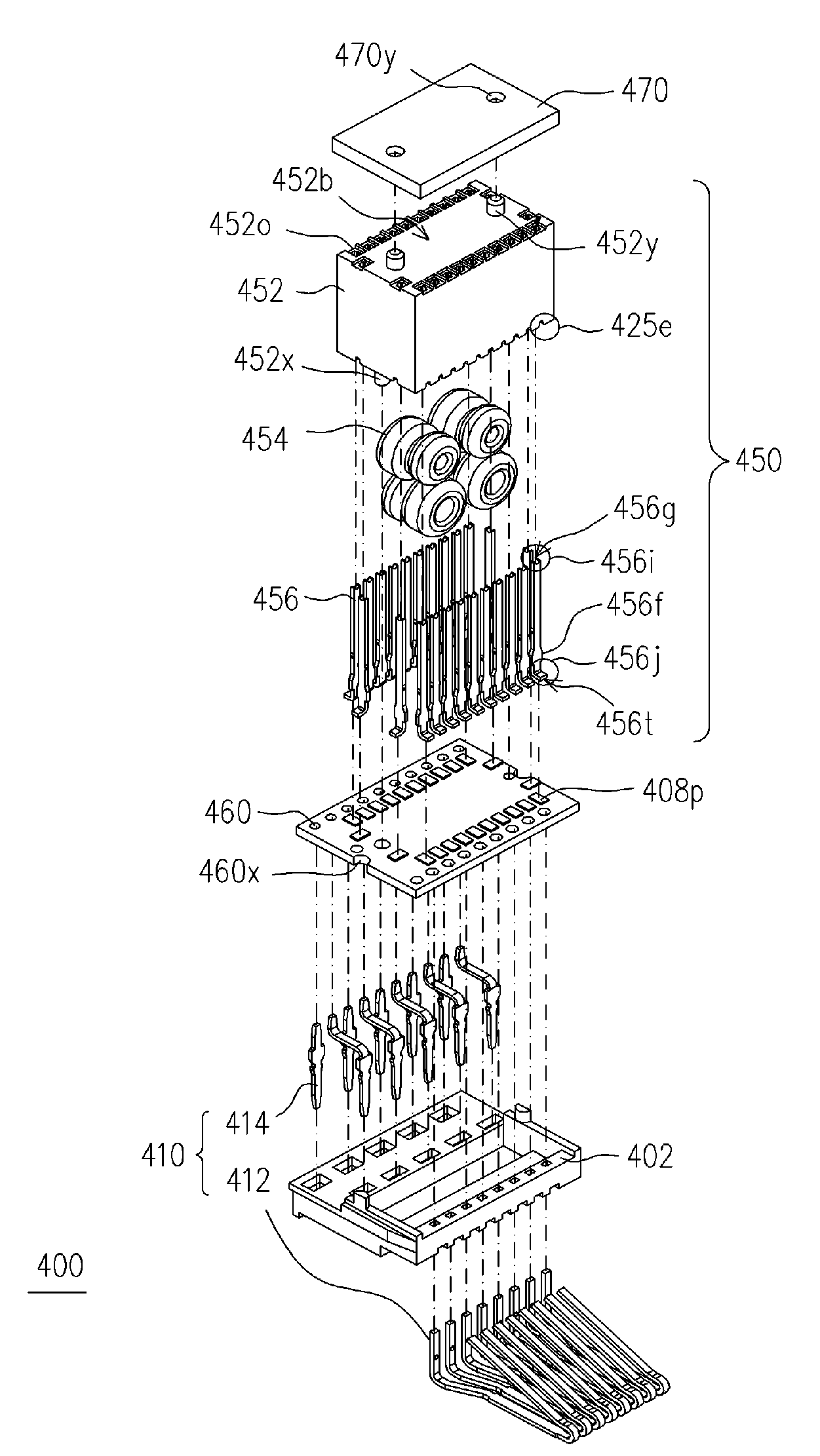
[0010]During the process of utilizing the auxiliary terminals to lead the conductive leads of the electronic component into the terminal channels of the holder, the auxiliary terminals rub with the conductive leads, such that wiping occurs between the auxiliary terminals and the conductive leads for removing the insulative layers cladding the conductive leads. The above design can effectively ensure the electrical connection between the auxiliary terminals and the conductive leads. Additionally, the auxiliary terminals and the terminal channels can firmly clamp the conductive leads, so as to ensure good reliability of the electrical connection therebetween and reduce the possibility of poor contact. Furthermore, the relative position between the auxiliary terminals and the conductive leads are fixed and the electrical connection therebetween is ensured by welding. The above feature of the present invention makes the welding between the auxiliary terminals and the conductive leads more reliable. Therefore, the electronic module disclosed by the present invention is suitable for mass production. Moreover, the fact that the conductive leads are led by the auxiliary terminals can prevent the conductive leads from being damaged by excessively great external forces.

Problems solved by technology

As the metal wire and board are difficult to be welded together, the product of U.S. Pat. No. 6,319,064 is unsuitable for mass production.
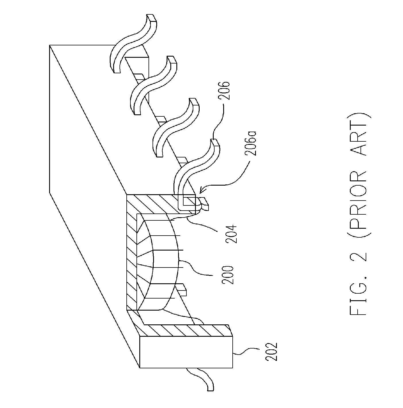
However, if the volume of the mount package is small, it is quite difficult to wrap the wire 204 on the notch 206a.
As for the above situation, the product of U.S. Pat. No. 5,656,985 is unsuitable for mass production.
However, the aforementioned connection between the conductive leads 304a and the terminals 300a can hardly achieve a satisfactory effect.

Method used


Image

  • Electronic module of electric connector
  • Electronic module of electric connector
  • Electronic module of electric connector

Examples


Embodiment Construction

[0020]The present invention provides an electronic module of an electric connector for solving the problems in the conventional art. The electronic module has an electronic component. The electronic component includes a plurality of conductive leads. As the relative position between the auxiliary terminals and the conductive leads is fixed, it is easy to weld the above two parts together, which (design) is advantageous to produce a large number of reliable electronic modules. Additionally, the auxiliary terminals lead the conductive leads to the aforementioned relative position to be electrically connected. Furthermore, while leading the conductive leads, the auxiliary terminals can simultaneously remove the insulative layers on the conductive leads, so as to simplify the removal process and hence to save the cost. The electronic module will be described in detail below.

[0021]FIG. 4 is a stereogram of an electric connector according to an embodiment of the present invention. FIG. 5 ...


PUM


Abstract

An electronic module of an electric connector suitable for being electrically connected to a terminal set inside the electric connector is provided. A plurality of connection terminals is installed on the terminal set for electrically connecting other devices. The electronic module includes: a holder having an accommodating space, wherein a plurality of terminal channels is disposed around and communicated with the accommodating space; at least one electronic component, disposed in the accommodating space of the holder, and having at least one conductive lead extending outside the accommodating space; and a plurality of auxiliary terminals with each having a connection end and an insertion end disposed in the terminal channels, wherein the insertion ends correspondingly inserted into the terminal channels lead the conductive leads into the terminal channels, so as to electrically connect the conductive leads. In addition, the connection ends are electrically connected to the connection terminals.

Description

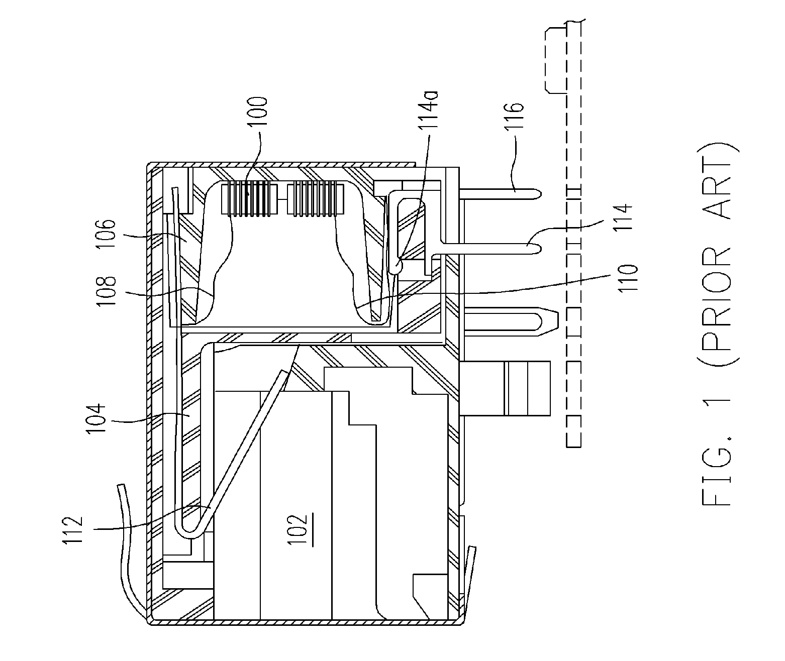
BACKGROUND OF THE INVENTION[0001]1. Field of Invention[0002]The present invention relates to an electronic module. More particularly, the present invention relates to an electronic module of an electric connector.[0003]2. Description of Related Art[0004]Generally, electronic apparatuses, such as notebooks, all require different electric connectors of various functions built therein, so as to, for example, electrically connecting a mother board to an electronic device, such as an external floppy disk drive. Besides electrically connecting two electronic devices, an electric connector also has other functions, such as filtering noises.[0005]FIG. 1 is a sectional view of a modular jack with filter insert and contact thereof disclosed by U.S. Pat. No. 6,319,064. Referring to FIG. 1, the electric connector has a built-in filter 100 disposed in a space defined by an insulative housing 102, an insulative insert 104 and a cap 106. Additionally, the filter 100 has a plurality of conductive l...

Claims


Application Information

Patent Timeline
IPC IPC(8): H01R13/66
CPCH01R13/6608H01R13/719H01R24/62
Inventor CHEN, LI-SENHSU, CHIEN-YUJIANG, ROBERT
Owner SPEED TECH
Learn More