
Apparatus and method for processing a substrate

a substrate and apparatus technology, applied in the direction of superimposed coating process, liquid/solution decomposition chemical coating, instruments, etc., can solve the problems of especially the manufacturing of large-sized flat display panels, and further affecting the yield of products, so as to improve the uniformity of line width and reduce the offset of wave crests

Active Publication Date: 2008-02-05
HANNSTAR DISPLAY CORPORATION
View PDF10 Cites 0 Cited by
  • Summary
  • Abstract
  • Description
  • Claims
  • Application Information

AI Technical Summary

Benefits of technology

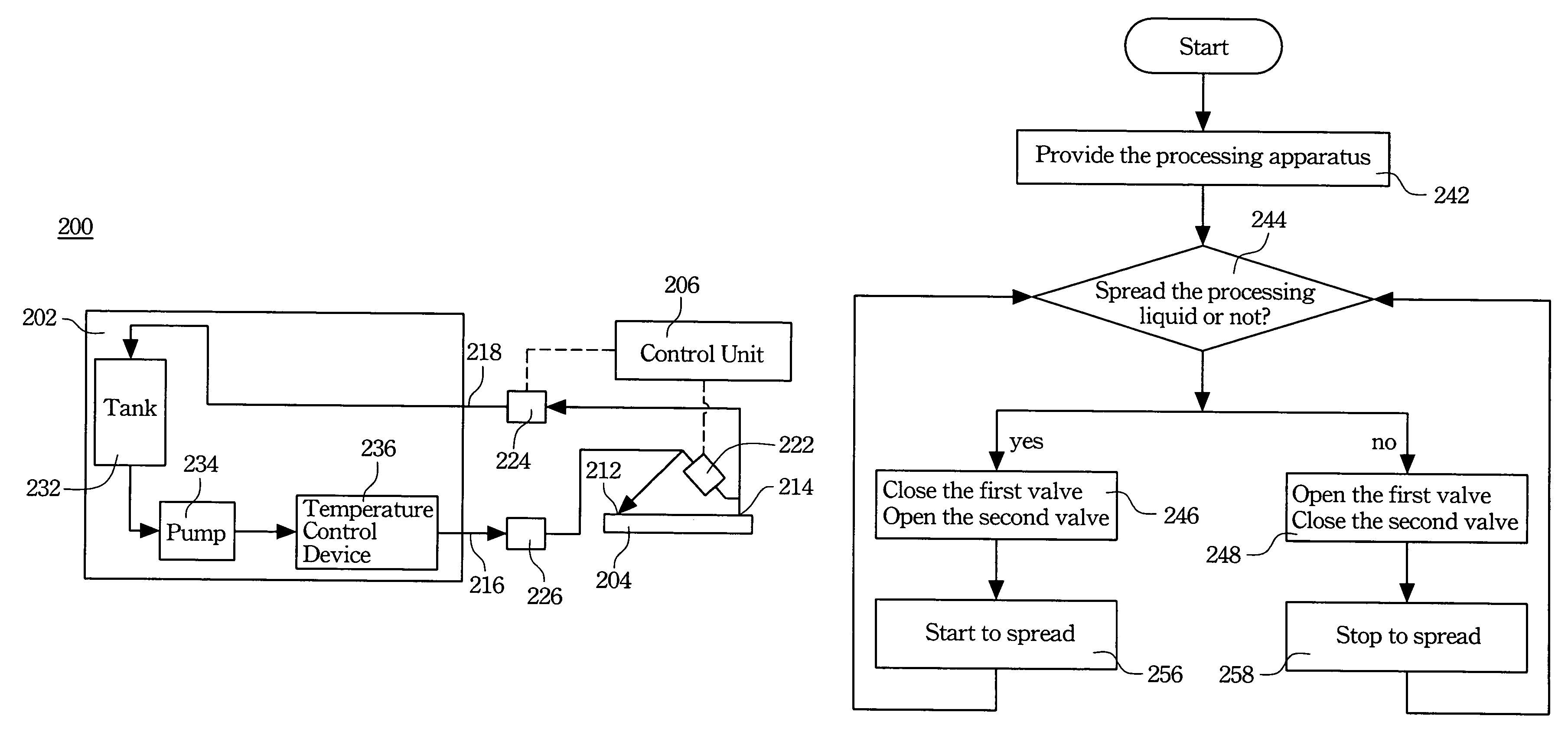
[0013]It is therefore an objective of the present invention to provide an apparatus for processing a substrate that modifies the original piping design of the nozzle unit to mitigate the offset of wave crest of processing liquid and improve the line width uniformity.
[0014]It is another objective of the present invention to provide a method for processing a substrate that balances the pressure applied on the processing liquid inside the two ends of the nozzle unit to decrease the offset of the wave crest of processing liquid.
[0017]The apparatus and method of the present invention are suitable for general substrate processing processes, such as the process for spreading developer solution or other processing liquids. The invention can easily balance the pressure applied on the processing liquid inside the two ends of the nozzle unit by modifying the original piping design of the nozzle unit, and therefore provides a cheap improving way. The invention mitigates the offset of wave crest of processing liquid, improves the line width uniformity, raises the yield of products and shortens the processing time.

Problems solved by technology

The offset of the wave crest causes suboptimal development such that the line width of the photoresist pattern is not uniform, and further affects the yield of products.
More particularly, this suboptimal development especially affects the manufacturing of large-sized flat display panels.

Method used


Image

  • Apparatus and method for processing a substrate
  • Apparatus and method for processing a substrate
  • Apparatus and method for processing a substrate

Examples


Embodiment Construction

[0026]Reference will now be made in detail to the present preferred embodiments of the invention, examples of which are illustrated in the accompanying drawings. Wherever possible, the same reference numbers are used in the drawings and the description to refer to the same or like parts.

[0027]FIG. 2A illustrates a process of one preferred embodiment of the present invention. In the preferred embodiment, a substrate processing apparatus 200 comprises a liquid supply unit 202, a nozzle unit 204, a first valve 224 and a second valve 222. The liquid supply unit 202 has an output port 216 and an input port 218, and a processing liquid is output from the output port 216. For examples, the processing liquid can be photoresist, developer solution, CMP (Chemical Mechanical Planarization) slurry, or further liquid crystals and so on.

[0028]The nozzle unit 204 has a first port 212, a second port 214 and a plurality of spreading units (not illustrated in FIG. 2A). The spreading unit, such as a n...


PUM

PropertyMeasurementUnit
lengthaaaaaaaaaa
lengthaaaaaaaaaa
temperatureaaaaaaaaaa

Abstract

An apparatus for processing a substrate has a liquid supply unit, a nozzle unit, a first valve and a second valve. The liquid supply unit has an output port and an input port, and a processing liquid is output from the output port. The nozzle unit has a first port and a second port, and the first port is connected to the output port of the liquid supply unit. The first valve is connected between the second port of the nozzle unit and the input port of the liquid supply unit. The second valve is connected between the second port of the nozzle unit and the output port of the liquid supply unit. Moreover, the switch states of the first and second valves are opposite in order to control whether the nozzle unit spreads the processing liquid on the substrate.

Description

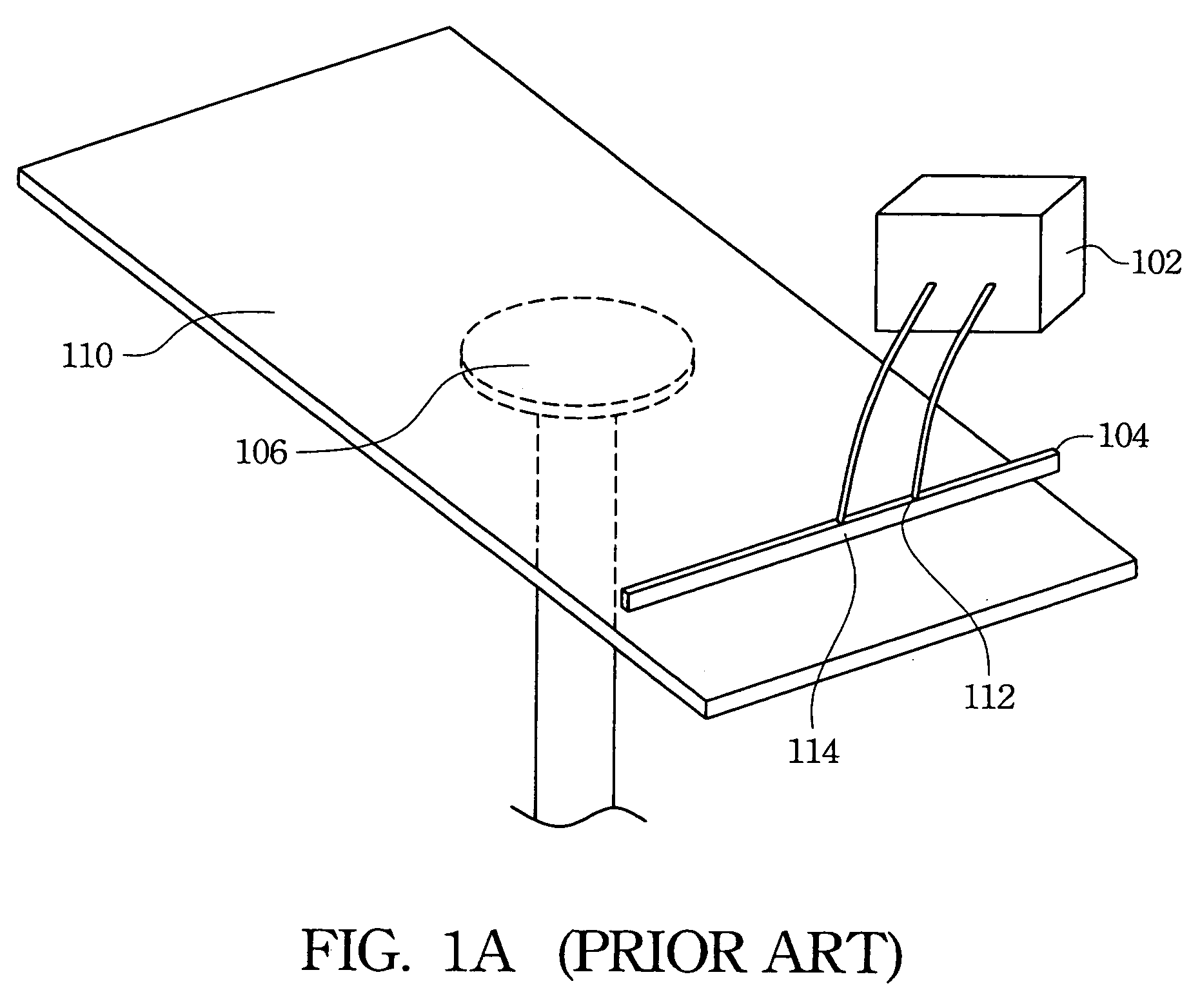
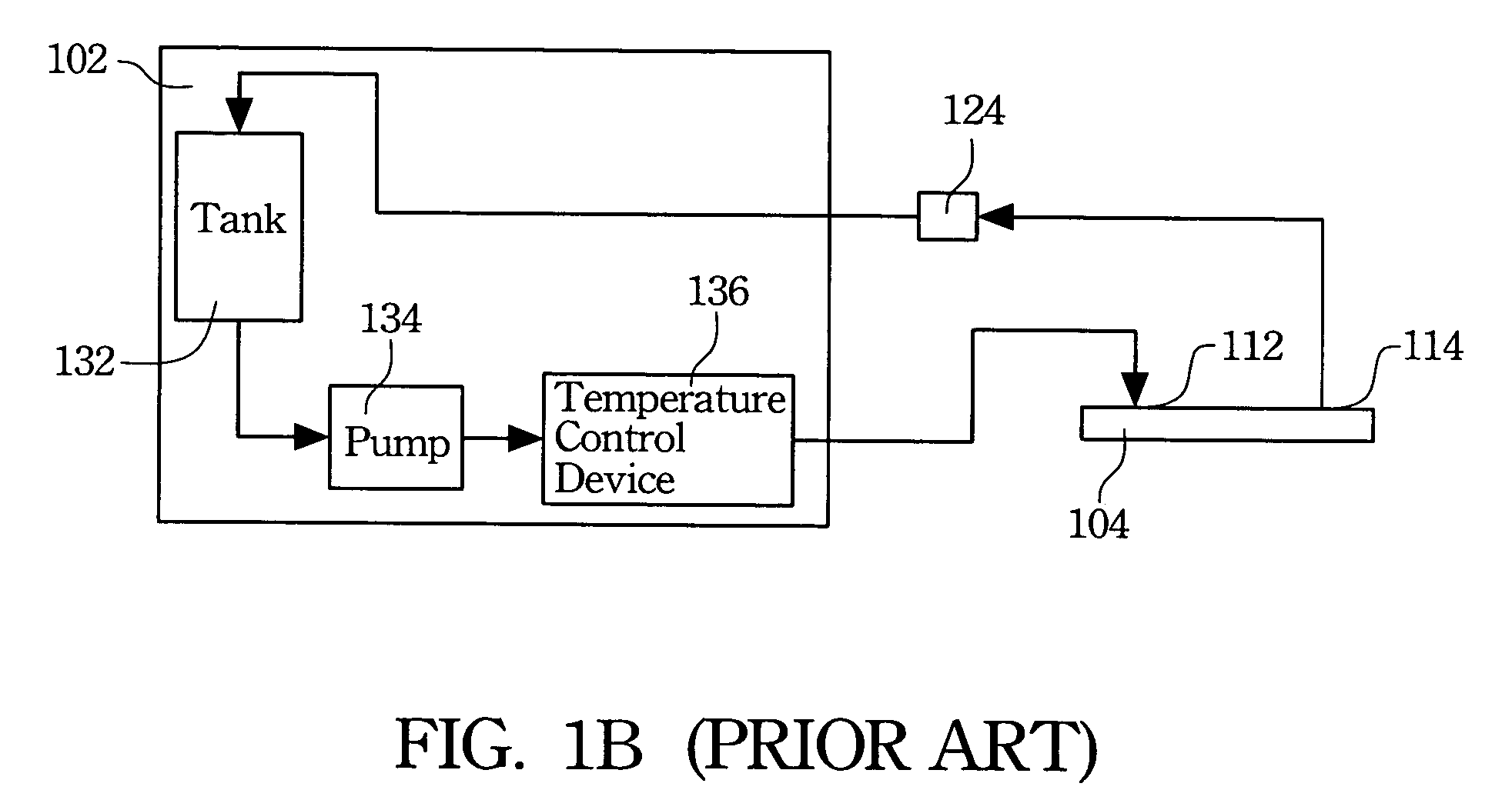
BACKGROUND[0001]1. Field of Invention[0002]The present invention relates to a substrate processing process. More particularly, the present invention relates to an apparatus and a method for spreading a processing liquid on the substrate.[0003]2. Description of Related Art[0004]Lithography is essential in the semiconductor process. Generally, the lithography process comprises the following steps: spreading a photoresist layer, exposing the photoresist layer to light, and developing the photoresist layer with a developer solution. For example, the photoresist layer of positive resists is exposed with UV light wherever the underlying material is to be removed. In these resists, exposure to the UV light changes the chemical structure of the resist so that it becomes more soluble in the developer. The exposed resist is reacted with the developer solution then washed away, leaving windows of the bare underlying material. On the other hand, negative photoresist behave in just the opposite ...

Claims


Application Information

Patent Timeline
Patent Type & Authority Patents(United States)
IPC IPC(8): B05C5/00B05B1/08B05B9/00B05C11/00B05C3/00C23C18/00G03F7/16
CPCC23C18/00G03F7/162
Inventor CHIANG, KUN-HSIANGYUAN, HUA-CHUN
Owner HANNSTAR DISPLAY CORPORATION
Learn More