

Optical submarine transmission system
a transmission system and optical submarine technology, applied in the direction of transmission monitoring, optical radiation measurement, instruments, etc., can solve the problems of cable faults in the land portion of cables, inability to switch to backup lines, and huge construction costs for cable b>11/b> and relay b>12/b> to be submerged
- Summary
- Abstract
- Description
- Claims
- Application Information
AI Technical Summary
Benefits of technology
Problems solved by technology
Method used
Image

Examples
first embodiment
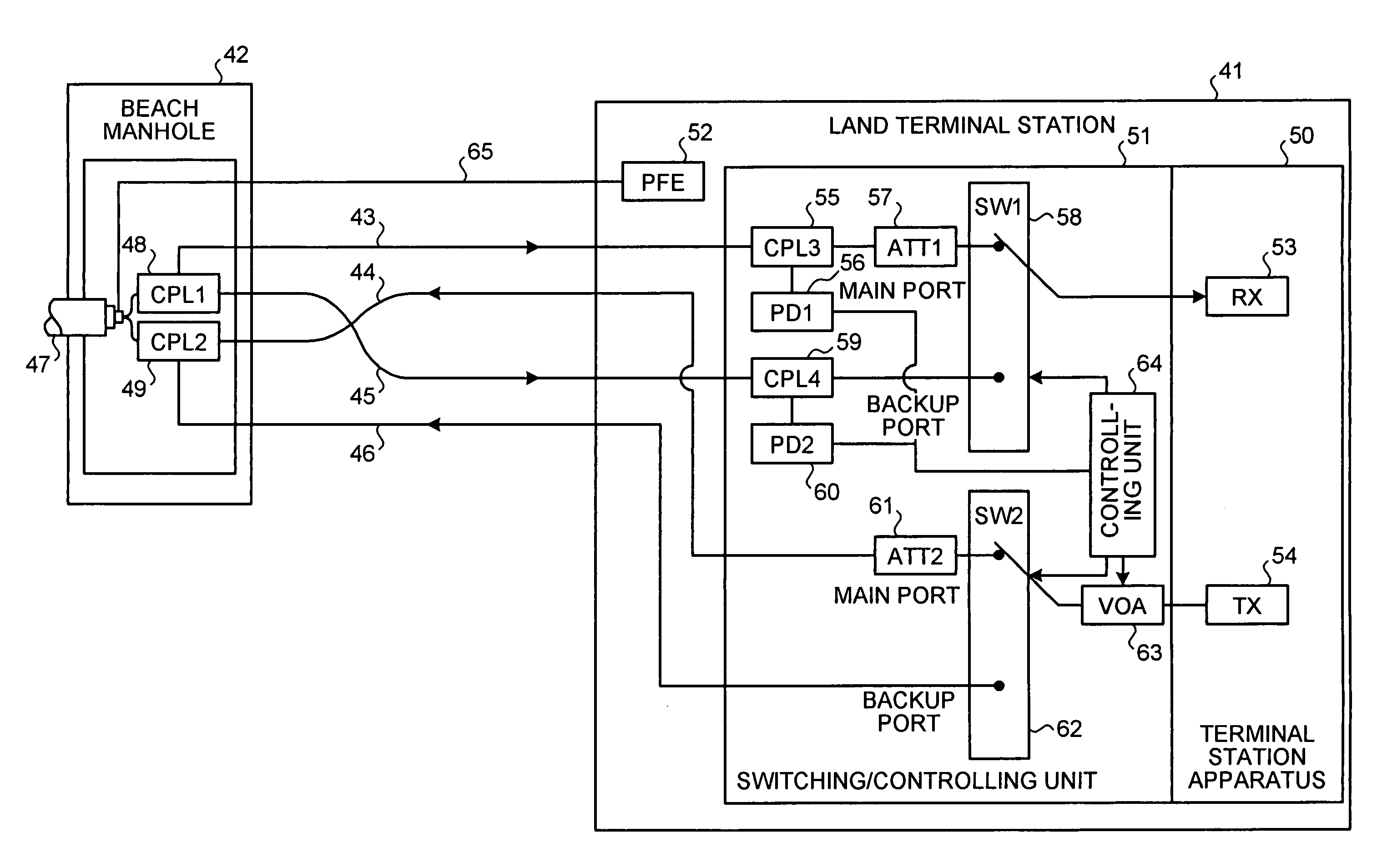
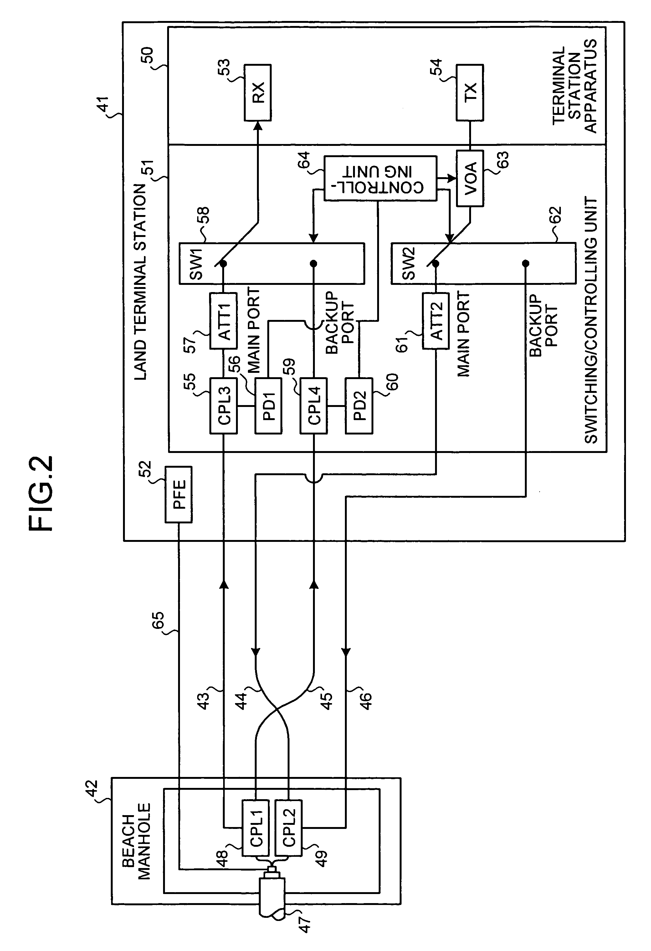
[0025]FIG. 2 is a block diagram of configuration of a land portion in an optical submarine transmission system according to a As shown in FIG. 2, a reception cable 43 (hereinafter, “main reception cable 43”) and a transmission cable 44 (hereinafter, “main transmission cable 44”) of a main line cable, and a reception cable 45 (hereinafter, “backup reception cable 45”) and a transmission cable 46 (hereinafter, “backup transmission cable 46”) of a backup line cable are laid between a land terminal station 41 and a beach manhole 42. The main line cables and the backup line cables are laid in geographically different routes.
[0026]A reception cable of a cable 47 in the underwater portion (hereinafter, “underwater cable 47”) is connected to an input terminal of a first optical coupler (CPL1) 48 provided in a beach manhole 42. The main reception cable 43 is connected to one output terminal of the first optical coupler 48. The backup reception cable 45 is connected to the other output termi...
second embodiment
[0054]The redundant configuration can also be realized for in an existing optical submarine transmission system. In such a case, the backup reception cable 45 and the backup transmission cable 46 are newly laid in a land portion; a beach manhole needs to be added only with the first and the second optical couplers 48, 49, the optical director 75, and the fiber grating 76; and a land terminal station needs to be added only with the first and the second photodiodes 56, 60, the first and the second optical attenuators 57, 61, the first and the second optical switches 58, 62, the variable optical attenuator 63, the controlling unit 64, the wavelength division multiplexer 71, the monitor signal output laser diode 72, and the first and the second optical demultiplexers 73, 74.
[0055]FIG. 7 is a block diagram of a configuration of a land portion in an optical submarine transmission system according to a third embodiment. As shown in FIG. 7, in the third embodiment, monitoring of the main r...
third embodiment
[0071]The redundant configuration can also be realized in an existing optical submarine transmission system. In such a case, the backup reception cable 45 and the backup transmission cable 46 are newly laid in a land portion; a beach manhole needs to be added only with the first and the second optical couplers 48, 49, the optical director 75, and the fiber grating 76; and a land terminal station needs to be added only with the first and the second photodiodes 56, 60, the first and the second optical attenuators 57, 61, the first and the second optical switches 58, 62, the variable optical attenuator 63, the controlling unit 64, the first and the second optical demultiplexers 73, 74, the first and the second wavelength division multiplexer 81, 83, the first and the second monitor signal output laser diodes 82, 84, the 1.31 μm optical filter 85, and the 1.32 μm optical filter 86.
[0072]According to the embodiments described above, a line in a land portion between a beach manhole and a...
PUM
 Abstract
Description
Claims
Application Information