Active resistance summer for a transformer hybrid

a transformer and active resistance technology, applied in the field of transmitting and receiving electrical signals, can solve the problems of signal distortion into the receive signal, limited signal dynamic range of transconductors, and conventional methods that are often inadequate for applications requiring signal recovery

Inactive Publication Date: 2008-02-05
MARVELL ASIA PTE LTD
View PDF329 Cites 10 Cited by
  • Summary
  • Abstract
  • Description
  • Claims
  • Application Information

AI Technical Summary

Problems solved by technology

As will be appreciated, these methods often introduce signal distortion into the receive signal.
Also, some transconductors have a limited signal dynamic range.
Accordingly, conventional methods are often inadequate for applications requiring signal recovery.
Additionally, known summing circuits, such as weighted summers using operational amplifiers, have not heretofore been modified to accommodate the intricacies associated with canceling transmit signals or regulating baseline wander (described below).
Removing DC components from a receive signal using transformer coupling can cause baseline wander.
Echoes can cause undue interference depending on the size of the reflection.
Accordingly, there are many signal-to-noise problems to be solved in the art.

Method used


Image

  • Active resistance summer for a transformer hybrid
  • Active resistance summer for a transformer hybrid
  • Active resistance summer for a transformer hybrid

Examples


Embodiment Construction

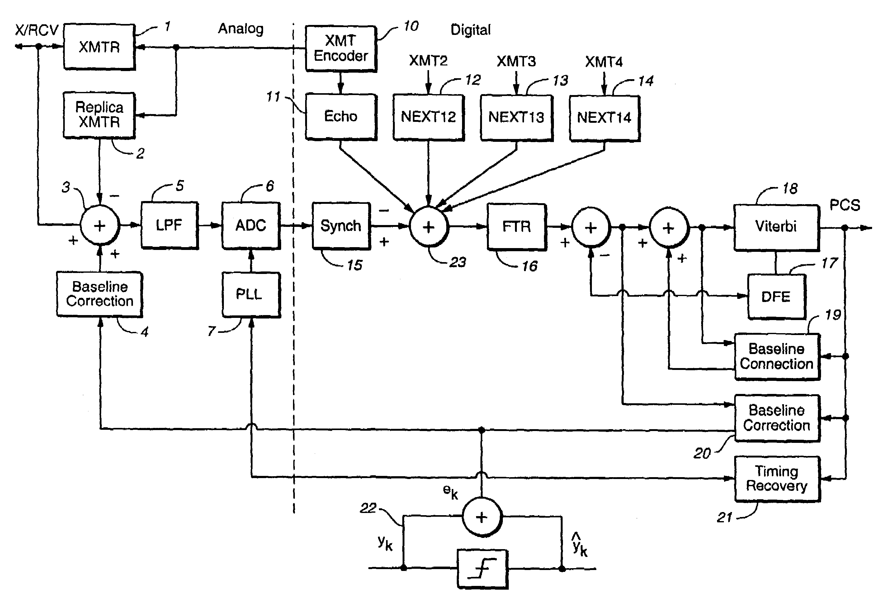
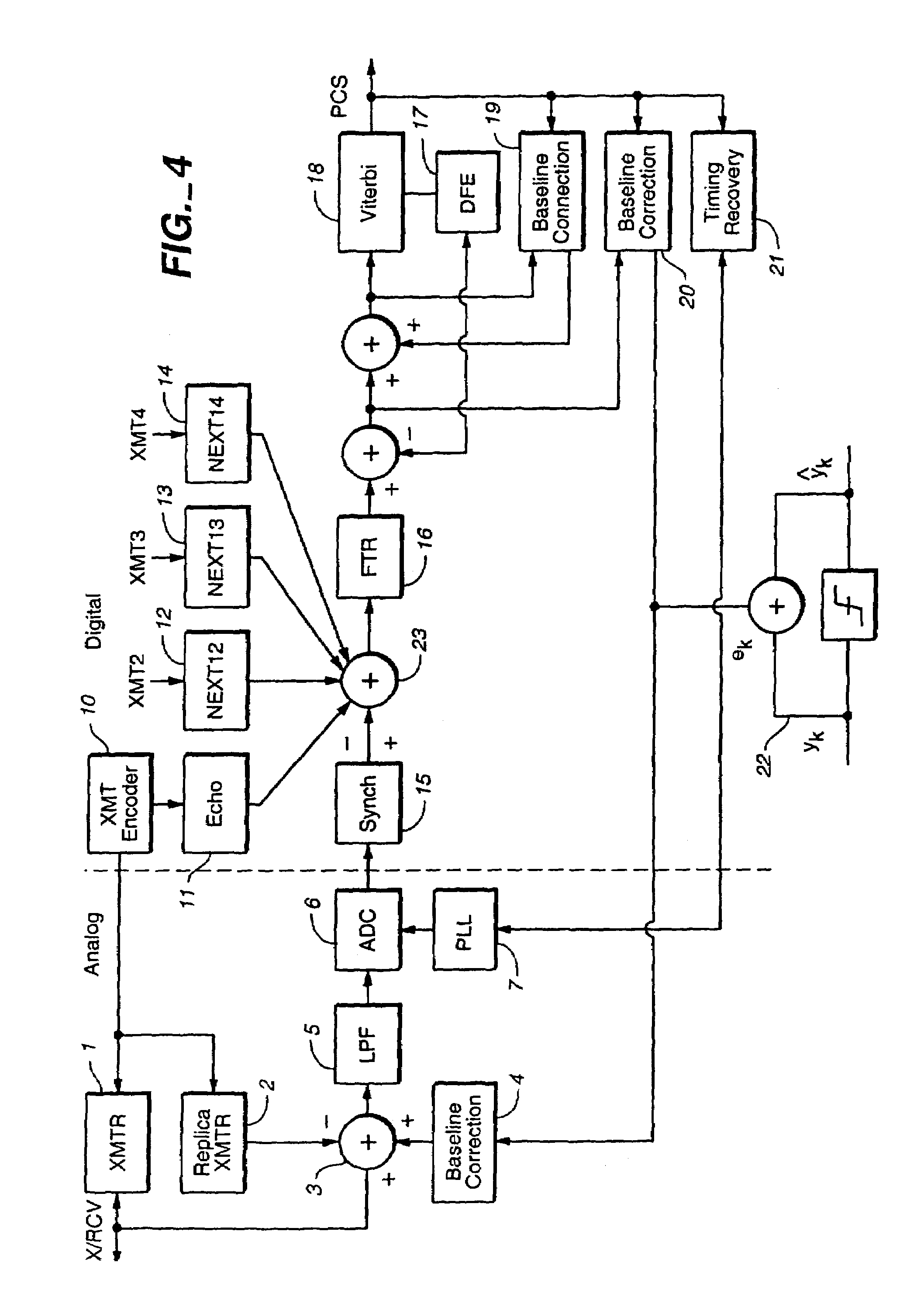
[0039]The preferred embodiments will be described with respect to a gigabit channel, as used, for example, in an Ethernet network; and to electrical circuits associated with separating transmit and receive signals in such a gigabit channel. The preferred embodiments will also be described with respect to baseline wander correction in such a gigabit channel. However, as will be appreciated by those skilled in the art, the present invention is also applicable to other transmission channels, and to other electrical circuits having applications requiring cancellation of transmit signals, for example.

[0040]FIG. 4 is a block diagram illustrating principle components for one of the four channels in a preferred gigabit channel configuration for use in an Ethernet network. As illustrated in FIG. 4, a vertical dashed line divides analog and digital processing components. The analog components preferably include a transmitter (“XMTR”) 1, replica transmitter (“Replica XMTR”) 2, transmit cancell...


PUM


Abstract

A transmit canceller comprises an operational amplifier having a first polarity input terminal, a second polarity input terminal, and an output terminal. A feedback element communicates with the second polarity input terminal and the output terminal. A first input resistor communicates with the second polarity input terminal and the measured signal input. A second input resistor communicates with the second polarity input terminal and the replica signal input. A predetermined voltage source communicates with the first polarity input terminal of the operational amplifier. The received signal is an output at the output terminal of the operational amplifier.

Description

CROSS-REFERENCE TO RELATED APPLICATIONS[0001]This application is a divisional of U.S. patent application Ser. No. 10 / 786,010 filed on Feb. 26, 2004, which is a Continuation of U.S. patent application Ser. No. 09 / 629,092 filed Jul. 31, 2000 now U.S. Pat. No. 6,775,529. The disclosures of the above applications are incorporated herein by reference.BACKGROUND OF THE INVENTION[0002]1. Field of the Invention[0003]The present invention relates generally to transmitting and receiving electrical signals through communication channels, such as a gigabit channel. In particular, the present invention relates to a transmit canceller that removes transmit signals from receive signals in such communication channels.[0004]2. Background and Related Art[0005]A gigabit channel is a communications channel with a total data throughput of one gigabit per second. A gigabit channel typically includes four (4) unshielded twisted pairs (hereinafter “UTP”) of cables (e.g., category 5 cables) to achieve this ...

Claims


Application Information

Patent Timeline
Patent Type & Authority Patents(United States)
IPC IPC(8): H04B1/10H04B1/38H04B3/20H04B1/58H04B3/23H04B3/32
CPCH04B1/581H04B3/23H04B3/32
Inventor ROO, PIERTE
Owner MARVELL ASIA PTE LTD
Why Eureka
Try Eureka