Communication environment measurement method for mobile station and the mobile station

a communication environment and measurement method technology, applied in the direction of radio transmission, transmission monitoring, electrical equipment, etc., can solve the problems of easy handover to the other cell, non-serving cell, increased interference, etc., to avoid generation of unnecessary handover, accurate judgment of communication environment quality, and avoidance of unnecessary handover

Inactive Publication Date: 2008-02-05
FUJITSU LTD
View PDF6 Cites 52 Cited by
  • Summary
  • Abstract
  • Description
  • Claims
  • Application Information

AI Technical Summary

Benefits of technology

[0040]It is another object of the present invention to prevent a drop in communication throughput by controlling handover such that an unnecessary handover is not generated.
[0041]It is still another object of the present invention to quickly control the transmission rate according to the communication environment by reporting a CQI value, based on the maximum SIR out of the SIRs measured for handover control, to the base station of the serving cells.
[0050]According to the present invention, the communication environment, such as SIR, between the serving cells / non-serving cells and a mobile station, can be measured under the same conditions, so the quality of the communication environment can be accurately judged and handover can be controlled based on this judgment, therefore handover can be executed at a correct timing.
[0051]Also according to the present invention, the communication environment, such as the SIR of receive signals, between the serving cells / non-serving cells and a mobile station, can be measured under the same conditions, so the quality of the communication environment can be accurately judged and handover can be controlled based on this judgment, therefore the generation of unnecessary handover can be avoided and a drop in the communication throughput can be prevented.
[0052]Also according to the present invention, a CQI value corresponding to the maximum SIR out of the SIRs measured for handover control is reported to the serving cell, so even if the serving cell is switched by handover, the transmission rate can be quickly controlled according to the communication environment of the serving cell.

Problems solved by technology

As a result, handover to the other cell which is an non-serving cell, is likely to occur easily.
As a result, the data is transmitted from the new serving cell to the mobile station via HS-PDSCH instead, and interference increases and the SIR value of the new serving cell tends to drop.

Method used


Image

  • Communication environment measurement method for mobile station and the mobile station
  • Communication environment measurement method for mobile station and the mobile station
  • Communication environment measurement method for mobile station and the mobile station

Examples


first embodiment

(A) First Embodiment

[0081]Configuration of Mobile Station

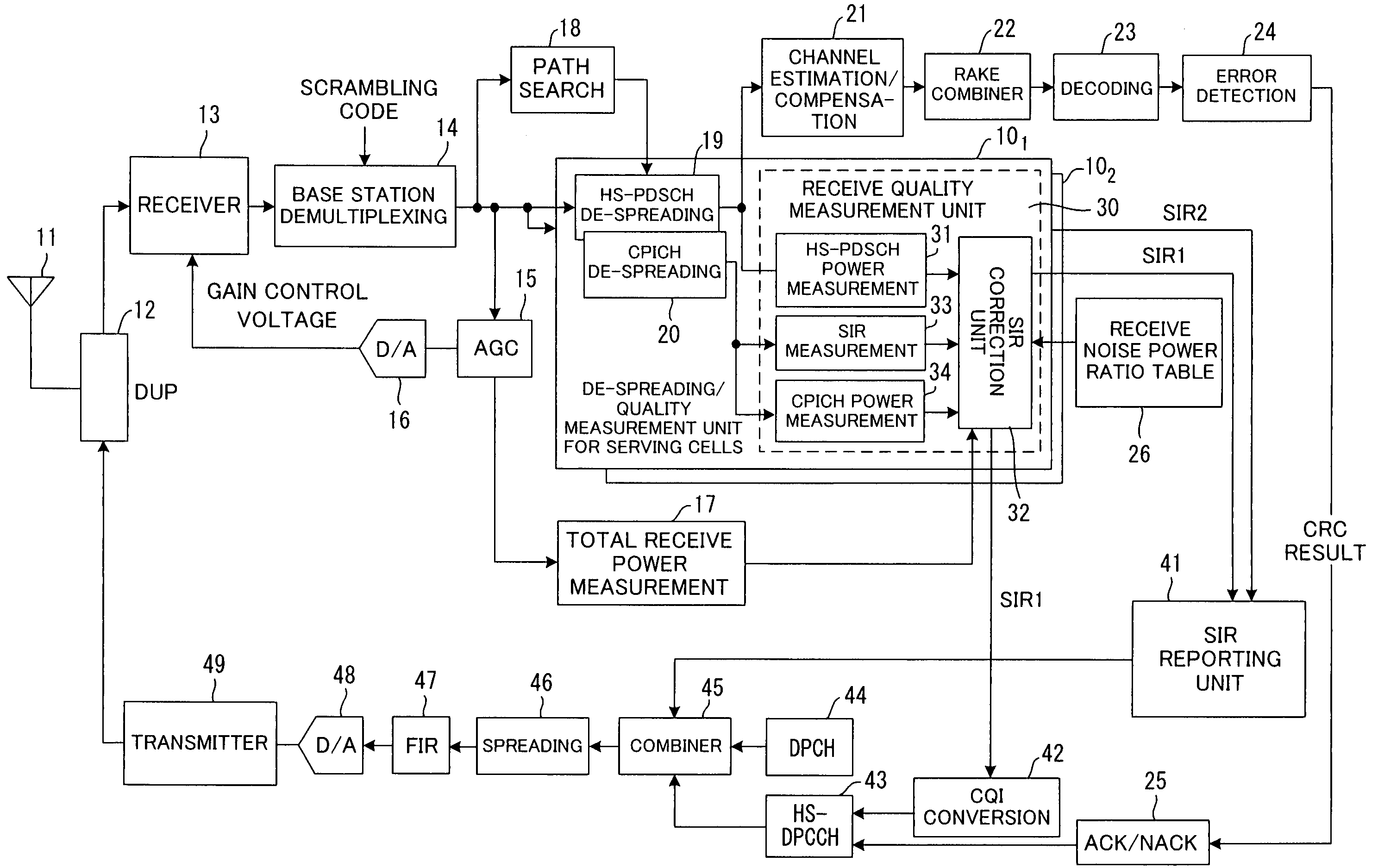
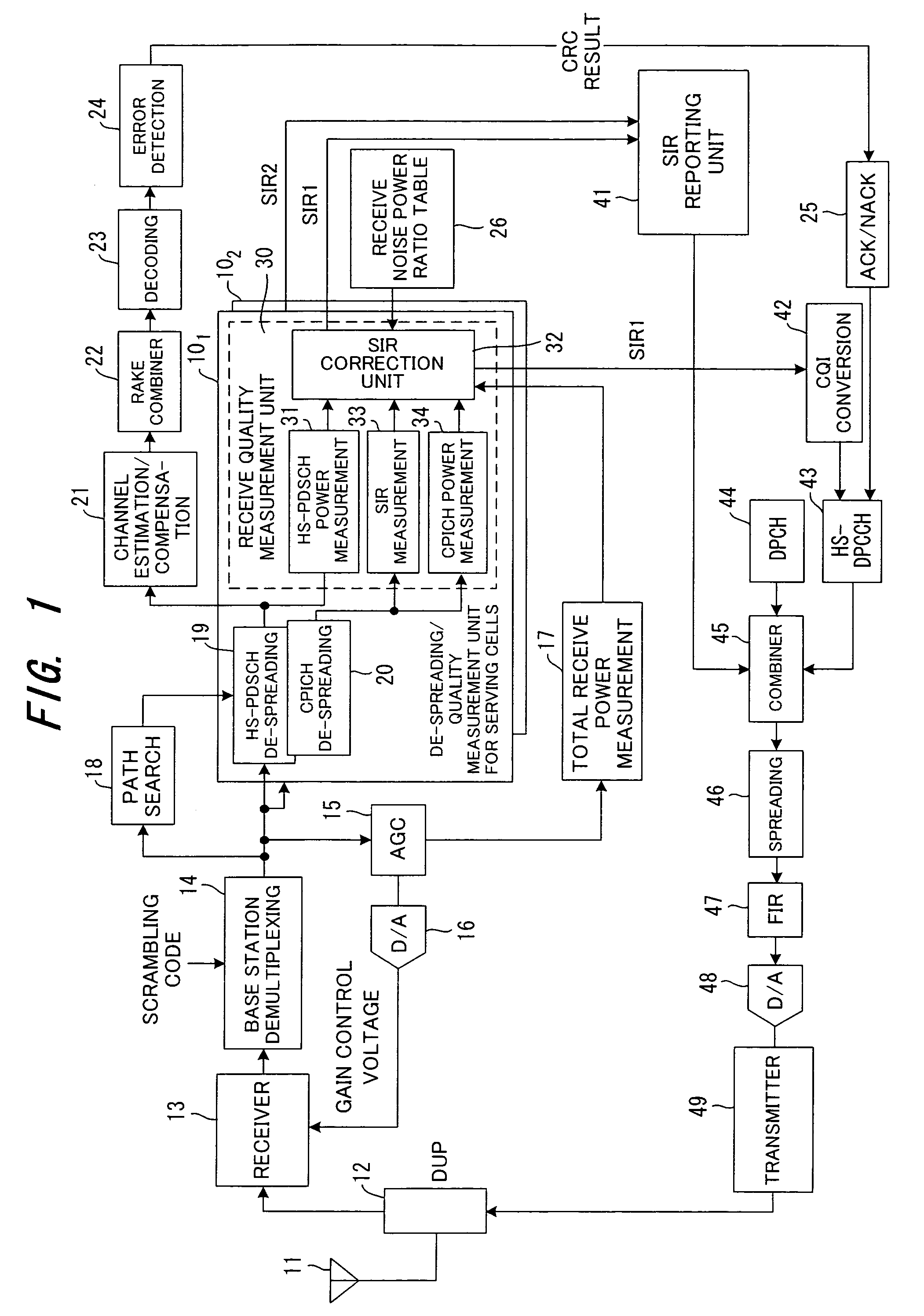
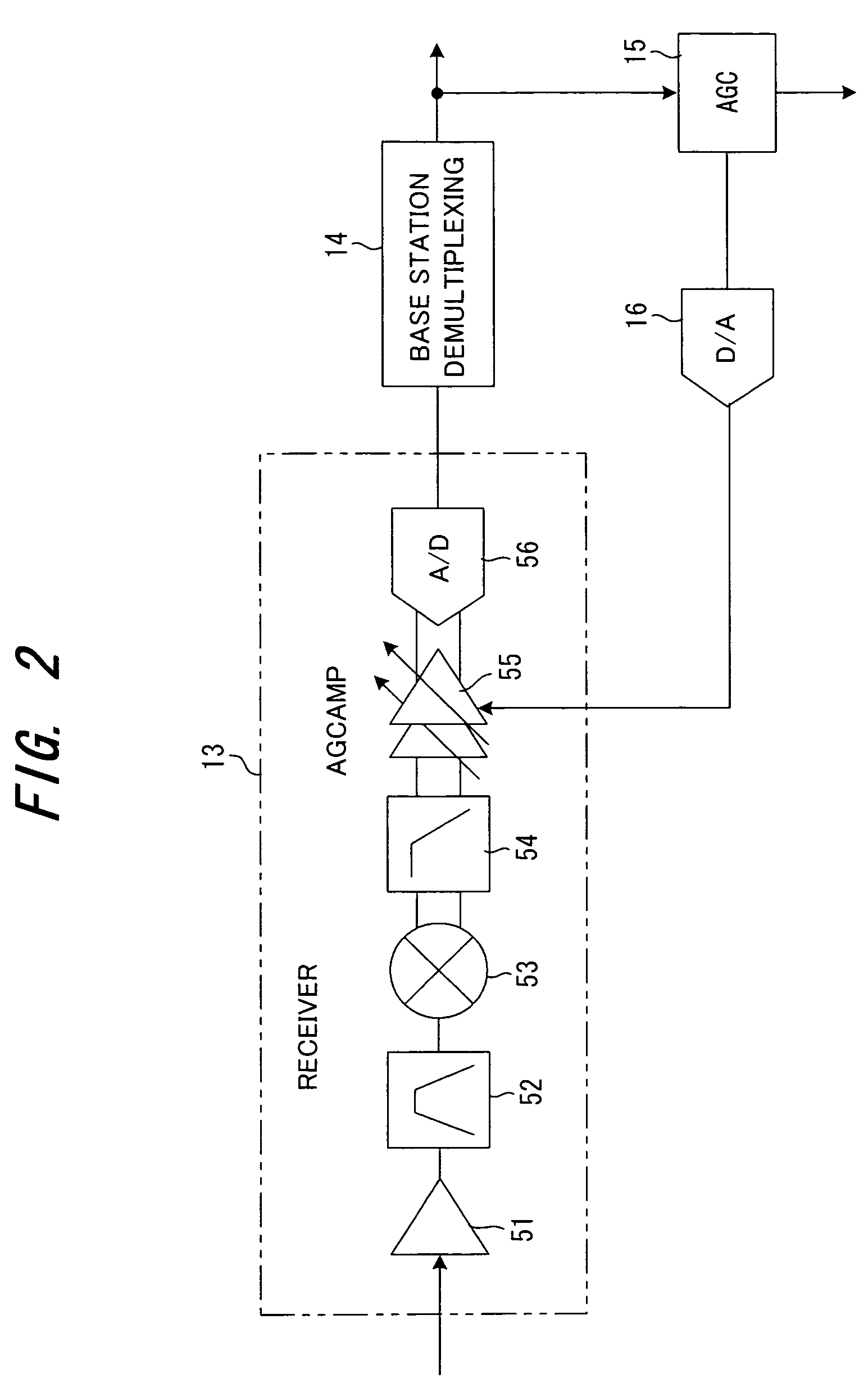
[0082]FIG. 1 is a block diagram depicting the mobile station of the present invention. The signal transmitted from the base station is input to the receiver 13 via the antenna 11 and the duplexer 12. As FIG. 2 shows, the receiver 13 comprises the high frequency amplifier 51, band pass filter 52 for limiting the band, frequency conversion unit 53 for converting RF signals into base band signals in frequency, low pass filter 54 for limiting the high band, gain variable amplifier 55 and AD converter 56 for converting input signals into analog signals.

[0083]The base station demultiplexing unit 14 multiplies the receiver output signal by the scrambling code of the serving cell or the adjacent non-serving cell (de-spreading) when necessary, demultiplexes the signals from a base station of each cell; and outputs them. The AGC control unit 15 determines the gain control value of the gain variable amplifier 55 (FIG. 2), so that the sig...

second embodiment

(B) Second Embodiment

[0105]In the first embodiment, SIR is estimated in a serving cell on assumption that data is not being received via HS-PDSCH, so that SIR can be measured and compared under the identical conditions for a serving cell and non-serving cell. In the second embodiment, SIR is estimated on assumption that data is being received from a non-serving cell via HS-PDSCH, so that SIR can be measured and compared under the identical conditions for a serving cell and non-serving cell.

[0106]FIG. 9 is a block diagram depicting the de-spreading / quality measurement units 101 and 102 of the serving cell and non-serving cell according to the second embodiment, where the elements that are same as the elements in the despreading / quality measurement unit in FIG. 1 are denoted with the same reference numerals. The differences are:

[0107](1) the SIR correction unit 32 is removed from the de-spreading / quality measurement unit 101 of the serving cell, and SIR measured by the SIR measurement...

third embodiment

(3) Third Embodiment

[0116]In the third embodiment, a mobile station demodulates HS-SCCH detects a slot which data is not being transmitted via HS-PDSCH, measures the SIR in the slot, and uses this SIR for handover, thereby the SIR measurement condition for the serving cell can be same as the condition of SIR measurement for the non-serving cell.

[0117]FIG. 12 is a block diagram of the third embodiment depicting the mobile station where elements that are same as the elements of the first embodiment in FIG. 1 are denoted with the same reference numerals. The differences are that an HS-SCCH measurement unit 40 is installed, and that the SIR measurement unit 33 measures the SIR in a slot where data is not being transmitted via HS-PDSCH, and outputs it as SIR1.

[0118]FIG. 13 is a flow chart depicting the handover control of the third embodiment. When the handover status is generated, the mobile station demodulates the data received from the serving cell SCL via HS-SCCH, and identifies a sl...


PUM


Abstract

In a communication system for respectively transmitting pilot signals from a plurality of base stations to a mobile station via a first channel and also for transmitting data from one base station to a mobile station via a second channel, the mobile station corrects total receive power at the time of handover by subtracting power of the data signal received via the second channel from the total receive power of the signals received from a base station in communication (serving cells) via the second channel, then corrects the total noise power based on the total receive power after the correction, and measures the communication environment between the base station and the mobile station using the power of the pilot signal received from the base station in-communication and the corrected total noise power.

Description

BACKGROUND OF THE INVENTION[0001]The present invention relates to a communication environment measurement method for a mobile station and a mobile station, and more particularly to a communication environment measurement method for a mobile station in a communication system where data is transmitted from one base station to the mobile station, and the mobile station.[0002]A W-CDMA (UMTS) mobile communication system is a radio communication system where a line is shared by a plurality of users, and comprises a core network 1, radio base station controllers (RNC: Radio Network Controller) 2 and 3, multiplexers / demultiplexers 4 and 5, radio base stations (Node B) 61-65 and mobile station (UE: User Equipment) 7, as FIG. 15 shows.[0003]The core network 1 is a network for routing in the mobile communication system, and the core network can be constructed by an ATM switching network, a packet switching network or a router network, for example. The core network 1 is also connected with a pu...

Claims


Application Information

Patent Timeline
Patent Type & Authority Patents(United States)
IPC IPC(8): H04B17/00H04B1/707H04W24/00H04W36/00H04W36/12H04W36/36H04W48/16H04W88/02
CPCH04W36/12H04W36/30H04W36/0085
Inventor NISHIKAWA, TAKUROUSUZUKI, MASAAKI
Owner FUJITSU LTD
Why Eureka
Try Eureka