Encoding device and decoding device

a technology of encoding device and decoding device, which is applied in the field of encoding and decoding digital audio data, can solve the problems of affecting the number of values, affecting the amount of data for transmission, and it is not realistic to transmit as many as 1,024 samples of spectral data via a low-rate transmission channel of, for instance, a portable phon

Active Publication Date: 2008-02-05
PANASONIC CORP
View PDF21 Cites 89 Cited by
  • Summary
  • Abstract
  • Description
  • Claims
  • Application Information

AI Technical Summary

Benefits of technology

[0023]With the above plurality of window spectrums composed of short blocks produced by the transforming unit in each frame cycle, adjacent window spectrums are likely to be similar to one another. When the judging unit judges that there is a similarity between the first and second window spectrums, a high frequency part of the first window spectrum is not quantized and encoded. Instead, this high frequency part is represented by a high frequency part of the second window spectrum. In more detail, the high frequency part of the first window spectrum is replaced with predetermined values. When values “0”, for instance, are used as the predetermined values, quantizing and encoding operations for this high frequency part are simplified. In addition, the bit amount of the high frequency part can be highly reduced.
[0025]The above decoding device receives at least one high frequency part of a window spectrum in each frame cycle, duplicates the high frequency part in accordance with the judgment by the judging unit, and uses the duplicated high frequency part as a high frequency part of other window spectrums. As a result, the present decoding device is capable of reproducing sound in the high frequency band at higher quality than a conventional decoding device.
[0031]When the above first quantizing unit produces, from certain sets of data near a peak in a window spectrum, sets of quantized data that have the same predetermined value, the second quantizing unit quantizes the certain sets of data by using a predetermined normalizing factor. As a result, the second quantizing unit produces sets of quantized data whose values are not consecutively the same predetermined value. That is to say, quantization by the second quantizing unit can correct an error caused in sets of spectral data near a peak in a window spectrum.
[0033]When the first quantizing unit of the encoding device produces, from certain sets of data near a peak in a window spectrum, sets of quantized data that have the same predetermined value, the second dequantizing unit of the decoding device roughly reconstructs the certain sets of data. That is to say, the second dequantizing unit corrects an error caused in sets of spectral data near a peak of a window spectrum. Consequently, the present decoding device is capable of reproducing sound near a peak of a window spectrum across the whole reproduction band more accurately than a conventional decoding device.

Problems solved by technology

The width of a reproduction band, however, affects the number of values of spectral data, which in turn affects the amount of data for transmission.
It is not realistic to transmit as many as 1,024 samples of the spectral data via a low-rate transmission channel of, for instance, a portable phone.
This intensifies the effect of quantization noise, so that sound quality decreases after encoding.

Method used


Image

  • Encoding device and decoding device
  • Encoding device and decoding device
  • Encoding device and decoding device

Examples


first embodiment

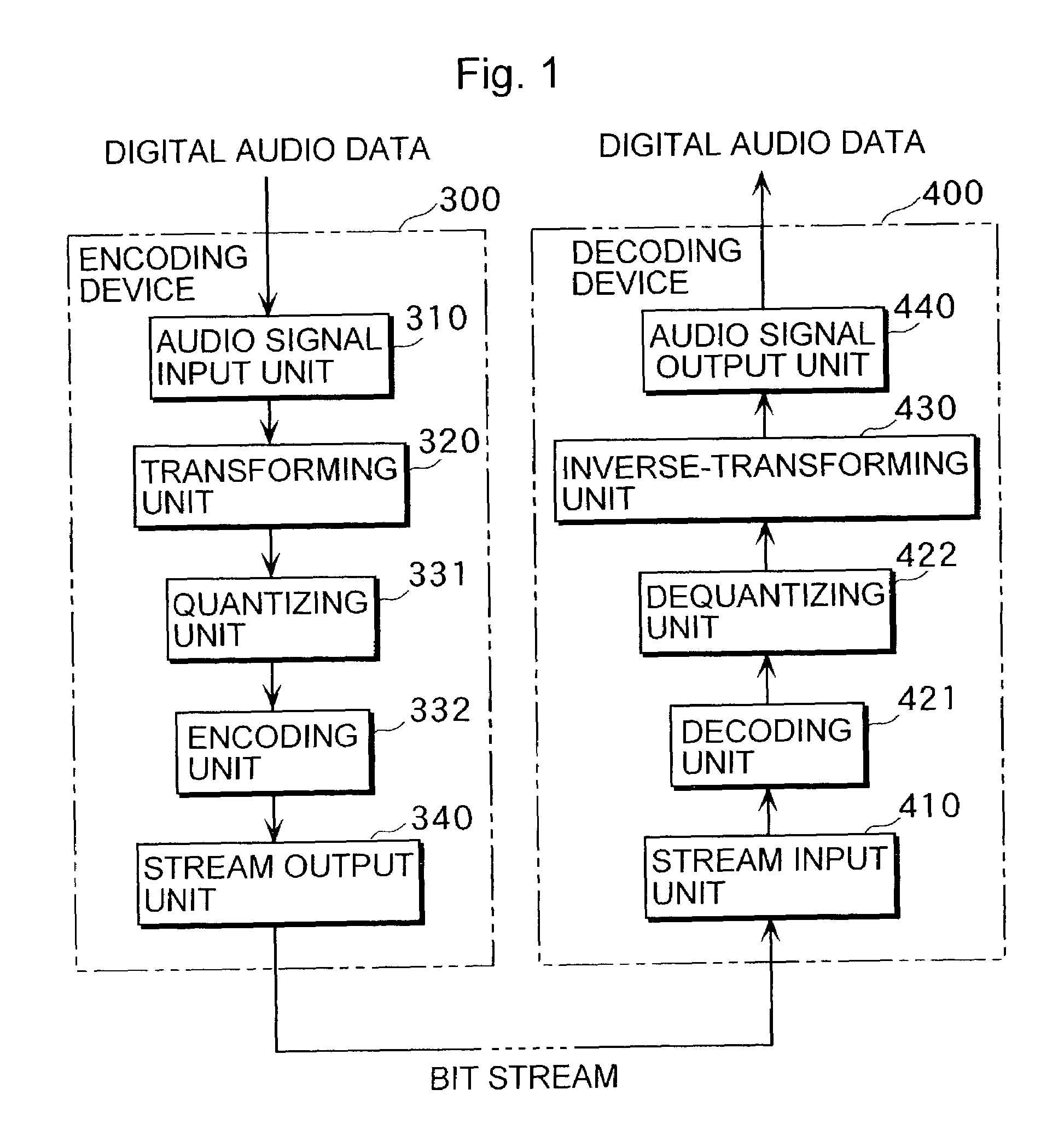
[0051]The following specifically describes an encoding device 100 and a decoding device 200 as embodiments of the present invention. FIG. 2 is a block diagram showing constructions of the encoding device 100 and the decoding device 200.

Encoding Device 100

[0052]This encoding device 100 effectively reduces the bit amount of an encoded audio bit stream before transmitting it. When the present encoding device 100 and a conventional encoding device produce encoded audio bit streams of the same amount of bits, an audio bit stream produced by the preset encoding device 100 can be reconstructed by the decoding device 200 as an audio signal at higher quality than an audio bit stream produced by the conventional encoding device. More specifically, the encoding device 100 reduces the bit amount of the encoded audio bit stream as follows. For short blocks, the encoding device 100 transmits eight blocks (i.e., windows) collectively with each window composed of 128 samples. When different sets of...

second embodiment

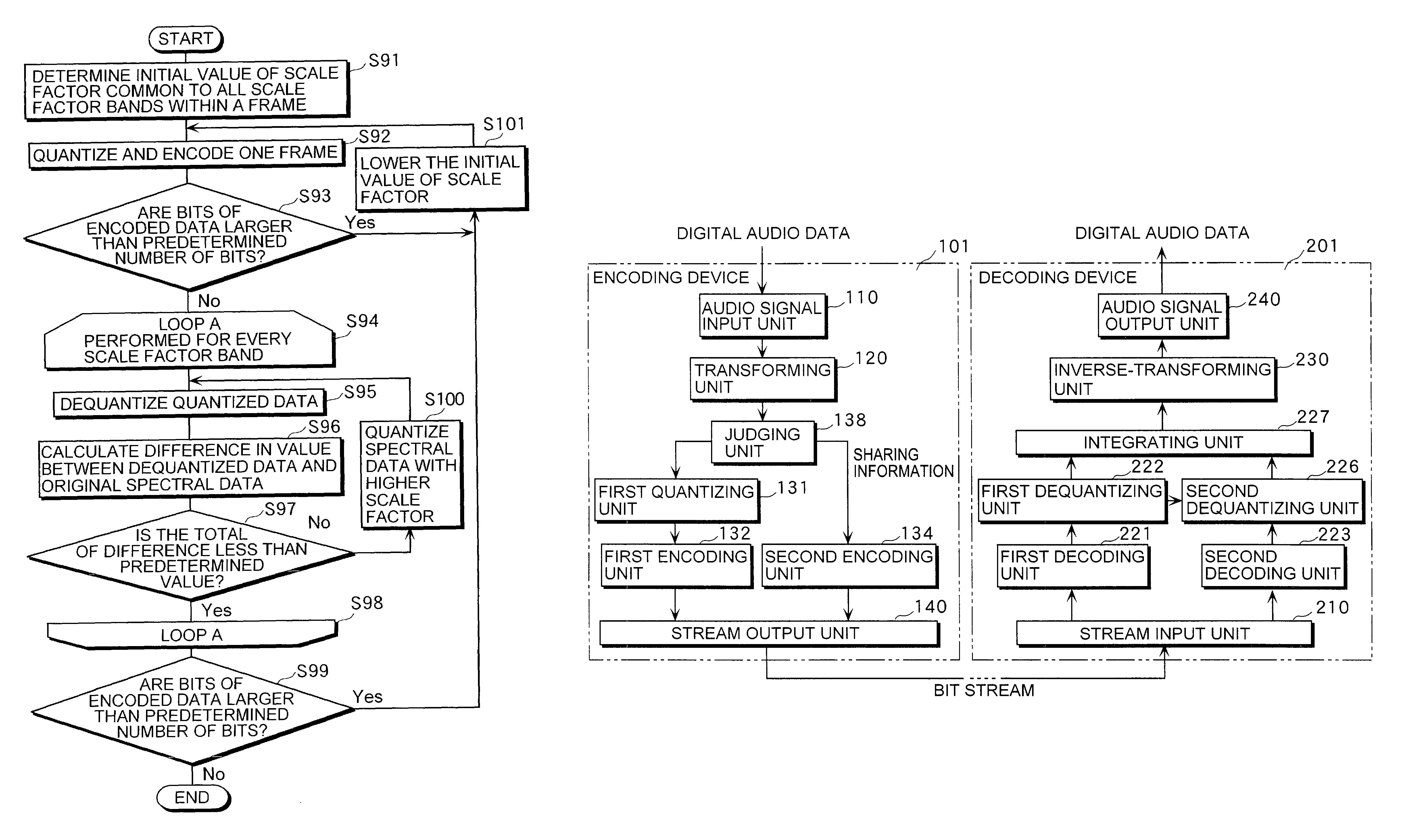
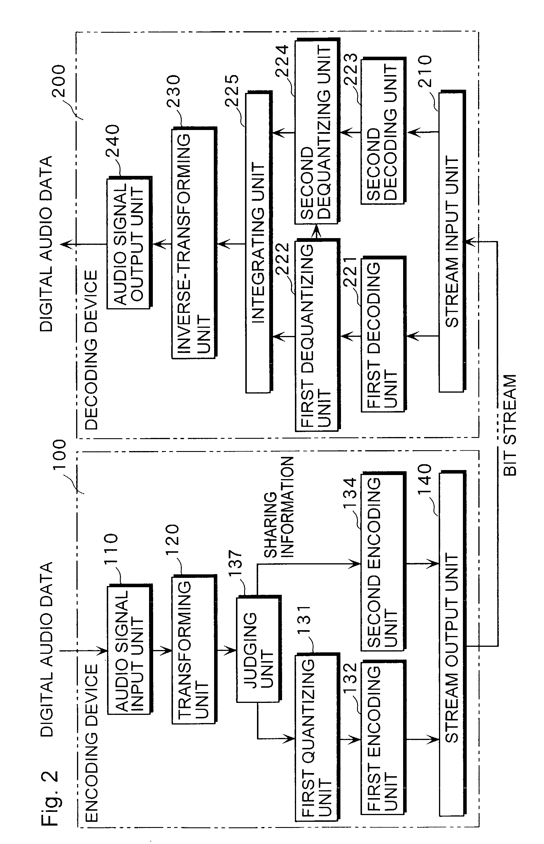
[0137]The following describes an encoding device 101 and a decoding device 201 of the second embodiment with reference to FIGS. 12 and 13 while focusing on features that are different from the first embodiment. FIG. 12 is a block diagram showing constructions of the encoding device 101 and the decoding device 201.

Encoding Device 101

[0138]When short blocks are used as MDCT block length, the encoding device 101 specifies two or more windows that include sets of spectral data that are similar to one another. The encoding device 101 then has a set of spectral data within one of the specified windows represent other sets of spectral data within other specified windows. In the present embodiment, a set of spectral data represents other sets of spectral data in a full frequency range. The encoding device 101 thus reduces the bit amount of the encoded audio bit stream. The encoding device 101 includes an audio signal input unit 110, a transforming unit 120, a first quantizing unit 131, a fi...

third embodiment

[0158]The following describes an encoding device 102 and a decoding device 202 of the third embodiment with reference to FIGS. 14˜17 with focus on features of the present embodiment that are different from the first embodiment. FIG. 14 is a block diagram showing constructions of the encoding device 102 and the decoding device 202.

Encoding Device 102

[0159]This encoding device 102 reconstructs spectral data, from which quantized data of the value “0” is generated, because this spectral data is adjacent to spectral data that has the highest absolute value. Spectral data processed by the encoding device 102 is based on long blocks. The reconstructed spectral data is then represented by data of a smaller bit amount to be transmitted to the decoding device 202. The encoding device 102 comprises an audio signal input unit 111, a transforming unit 121, a first quantizing unit 151, a first encoding unit 152, a second quantizing unit 153, a second encoding unit 154, and a stream output unit 1...


PUM


Abstract

An encoding device includes a transforming unit operable to extract a part of an inputted audio signal at predetermined time intervals and to transform each extracted part to produce a plurality of windows composed of short blocks, and a judging unit operable to compare the windows with one another to judge whether there is a similarity of a predetermined degree and to replace a high frequency part of a first window, which is one of the produced windows, with values “0” when there is the similarity, wherein the first window and a second window share a high frequency part of the second window, which is also one of the produced windows. The encoding device also includes a first quantizing unit operable to quantize the produced windows after replacing operation; a first encoding unit operable to encode the quantized windows to produce encoded data; and a stream output unit operable to output the produced encoded data.

Description

TECHNICAL FIELD[0001]The present invention relates to technology for encoding and decoding digital audio data.BACKGROUND ART[0002]In recent years, a variety of audio compression methods have been developed. MPEG-2 Advanced Audio Coding (MPEG-2 AAC) is one of such compression methods, and is defined in detail in “ISO / IEC 13818-7 (MPEG-2 Advanced Audio Coding, AAC)”.[0003]The following describes conventional encoding and decoding procedures with reference to FIG. 1. FIG. 1 is a block diagram showing a conventional encoding device 300 and a conventional decoding device 400 conforming to MPEG-2 AAC. The encoding device 300 receives and encodes an audio signal in accordance with MPEG-2 AAC, and comprises an audio signal input unit 310, a transforming unit 320, a quantizing unit 331, an encoding unit 332, and a stream output unit 340.[0004]The audio signal input unit 310 receives digital audio data that has been generated as a result of sampling at a 44.1-kHz sampling frequency. From this...

Claims


Application Information

Patent Timeline
Patent Type & Authority Patents(United States)
IPC IPC(8): G10L19/00G10L19/02G10L21/038
CPCG10L19/0208G10L21/038
Inventor NISHIO, KOSUKENORIMATSU, TAKESHITSUSHIMA, MINEOTANAKA, NAOYA
Owner PANASONIC CORP
Why Eureka
Try Eureka