
Centre line multidimensional suspension system

a multi-dimensional suspension and center line technology, applied in the field of new apparatus, can solve problems such as positive interference between, and achieve the effects of reducing the likelihood of flipping and stalling, facilitating folding, and high flip ratio multipl

Inactive Publication Date: 2008-02-12
FTL SEALS TECH
View PDF13 Cites 28 Cited by
  • Summary
  • Abstract
  • Description
  • Claims
  • Application Information

AI Technical Summary

Benefits of technology

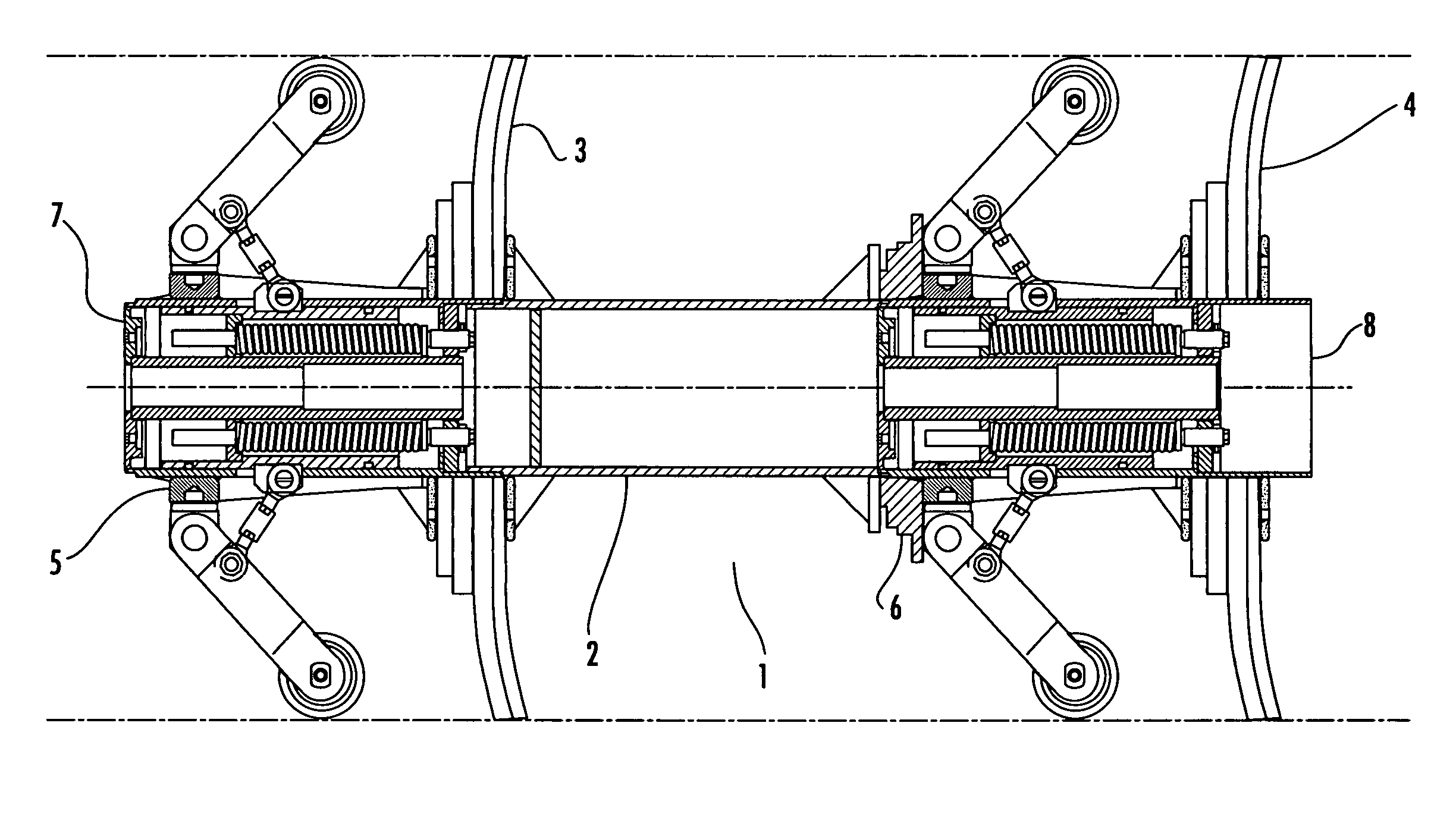
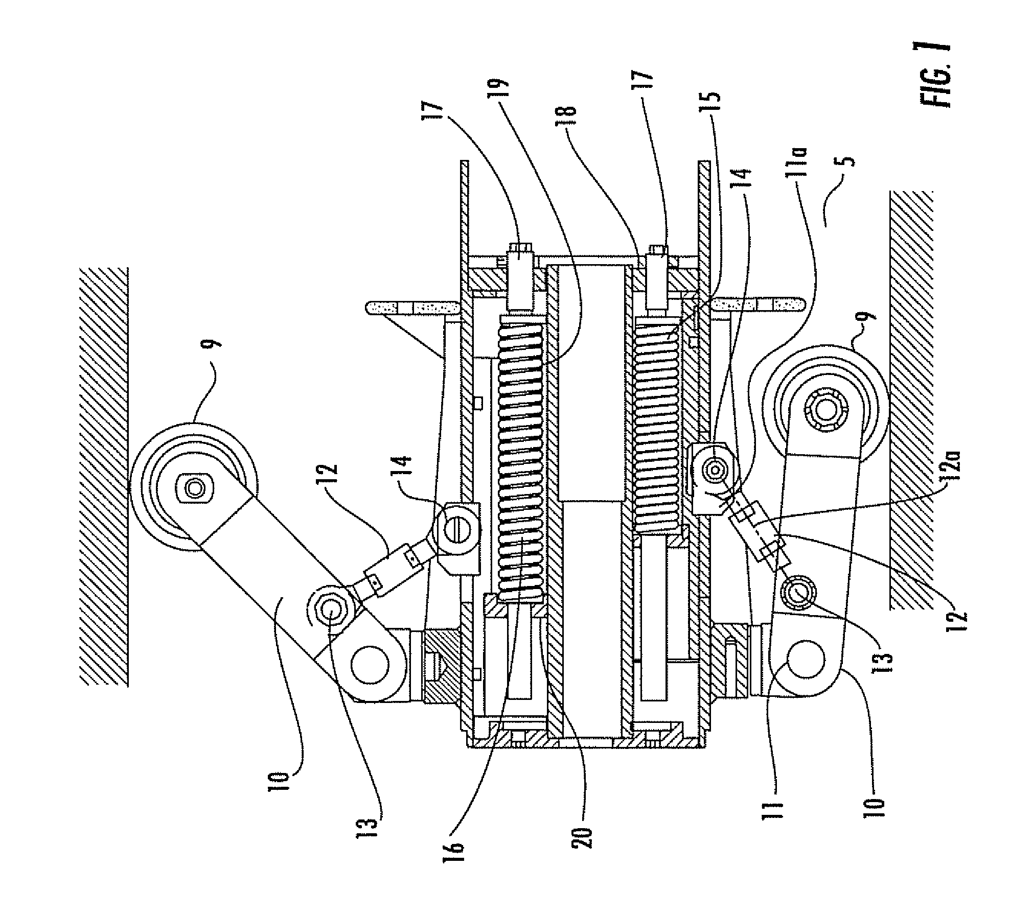
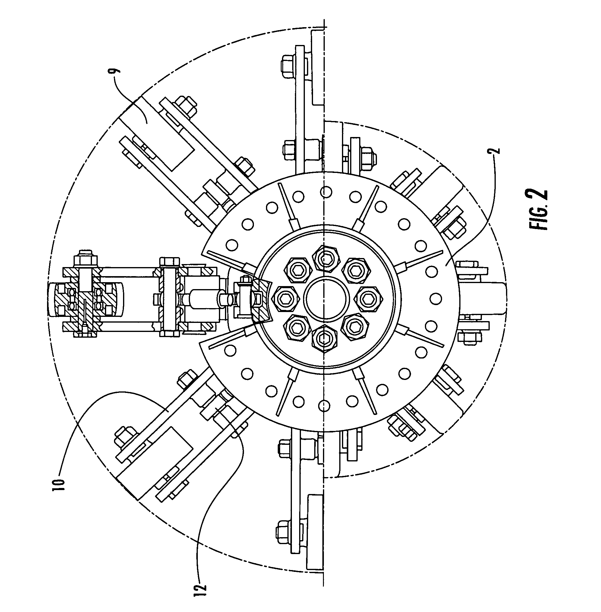
"The invention is a new suspension system for a pipeline pig that can be used in cleaning and inspection of pipelines. The system is designed to fit pigs of various diameters and can adjust to the inner wall of the pipe to prevent uneven wear and friction. The system uses a plurality of wheels that are concentrically mounted around a biasing means, such as a piston, which is operable in a direction coplanar with the pig shaft. This design allows for a more efficient and effective pig that can be used in subsea and land applications."

Problems solved by technology

In a dewatering, RFO (ready for operations) or cleaning pig, the diameter of the sealing disc is such that it creates a positive interference between the inner walls of the pipe and the outer surface of the sealing disc.

Method used


Image

  • Centre line multidimensional suspension system
  • Centre line multidimensional suspension system
  • Centre line multidimensional suspension system

Examples


example 1

Suspension Geometry and Force Calculations for a Typical 28 to 42 Inch (71.12 cm to 106.68 cm) System.

[0072]FIG. 8 illustrates Centreline Suspension Geometry

[0073]

W = force at wheel(s)a = Effective link length 75.8765 mmR = load in turn-buckleI = overall arm lengthF = Spring (piston force)φ = angle between turnbuckle and piston CLQh = Hor. force onΦ = angle between pivot to body mountingmountingblock CLQv = Ven. force onΨ = Angle between arm CL and piston CLmountingα = Difference between θ and ψ;constant = 8.7175°Note:Point B is constrained to move horizontally by the inner piston assembly, whilst the arm pivots about point 0.

[0074]Take moments about position O for link AO

W*1*Cos ψ=R*a*Sin(θ+φ)  a)

but resolving R horizontally at B we get

R*Cos φ=F  b)

or

R=F / Cos φ  c)

substitute c) into a)

W*1*Cos ψ=F / Cos φa Sin(θ+φ)

rearranging gives

W=F*a*Sin(θ+φ) / Cos ψ / Cos φ  d)

[0075]Simplifying gives

W=F*k where k=Sin(θ+φ) / 1 / Cos ψ / Cos φ  e)

[0076]Referring to Table 2 below and calculating k we get NB θ=ψ...

example 2

Suspension Modules Material Selection for a Typical 28 to 42 Inch (71.12 cm to 106.68 cm) Suspension System.

The Main Body of the Modules.

[0083]The material selected for the main body of the suspension modules is a drawn over mandrel (DOB) cylinder tube ref. ASTM A513 grade 1026. The drawn tube has a tensile strength figure of 585 N / mm2. The other components fabricated onto the body are BS970:080M50 (EN43A).

[0084]The finished body is phosphated all over and the external surfaces are xylan 1070 coated.

The Piston.

[0085]The material selected for the piston is BS970:080M50. The piston comprises a main tube and a welded in flange of the same material. The finished piston is phosphated and xylan 1070 coated.

The Suspension Linkage Mechanism.

[0086]The majority of the suspension linkage components are manufactured from BS970:708M40 which is heat treated to condition R. This gives a tensile strength 700 / 850 N / mm2 and a hardness value of 201 / 255 HB. The components that are not manufactured from...


PUM


Abstract

There is described a novel apparatus for use in connection with pipe cleaning and monitoring systems. The apparatus is a suspension system adapted to fit a pipeline pig shaft, the pig being provided with a plurality of wheels. The wheels are concentrically mounted around a biasing means which is operable in a direction coplanar with the pig shaft. There is also described a pipeline pig comprising the suspension system and a method of cleaning a pipeline.

Description

CROSS-REFERENCE TO RELATED APPLICATIONS[0001]The present application is a continuation of U.S. patent application Ser. No. 09 / 937,413, filed Mar. 20, 2002, now abandoned, which is a U.S. national phase application of PCT International Application No. PCT / GB00 / 01159, having an international filing date of Mar. 28, 2000 and claiming priority to Great Britain Application Nos. 9907145.8 and 0001351.6 filed Mar. 29, 1999 and Jan. 21, 2000. The above PCT International Application was published in the English language and has International Publication No. WO 00 / 58660.BACKGROUND OF THE INVENTION[0002]This invention relates to a novel apparatus for use in connection with pipe cleansing and monitoring systems.SUMMARY OF THE INVENTION[0003]In particular the invention relates to a novel suspension system for use in relation to pipeline pigging apparatus, for pipes ranging in diameter from as small as 6 inches (15.24 cm) to as large as 56 inches (142.24 cm), although the system could fit into pi...

Claims


Application Information

Patent Timeline
Patent Type & Authority Patents(United States)
IPC IPC(8): B08B9/055B08B9/04F16LF16L55/28
CPCF16L55/28B08B9/0551B08B9/0557
Inventor SMITH, STEVESYKES, SIMON
Owner FTL SEALS TECH
Learn More