
Sliding door opening and closing device

a technology for sliding doors and openings, applied in the direction of doors, roofs, wing accessories, etc., can solve the problems of increased design costs and reduced layout flexibility, and achieve the effect of reducing the height of the floor of the vehicle body and improving the appearance of the vehicl

Inactive Publication Date: 2008-02-12
MITSUBA CORP
View PDF20 Cites 11 Cited by
  • Summary
  • Abstract
  • Description
  • Claims
  • Application Information

AI Technical Summary

Benefits of technology

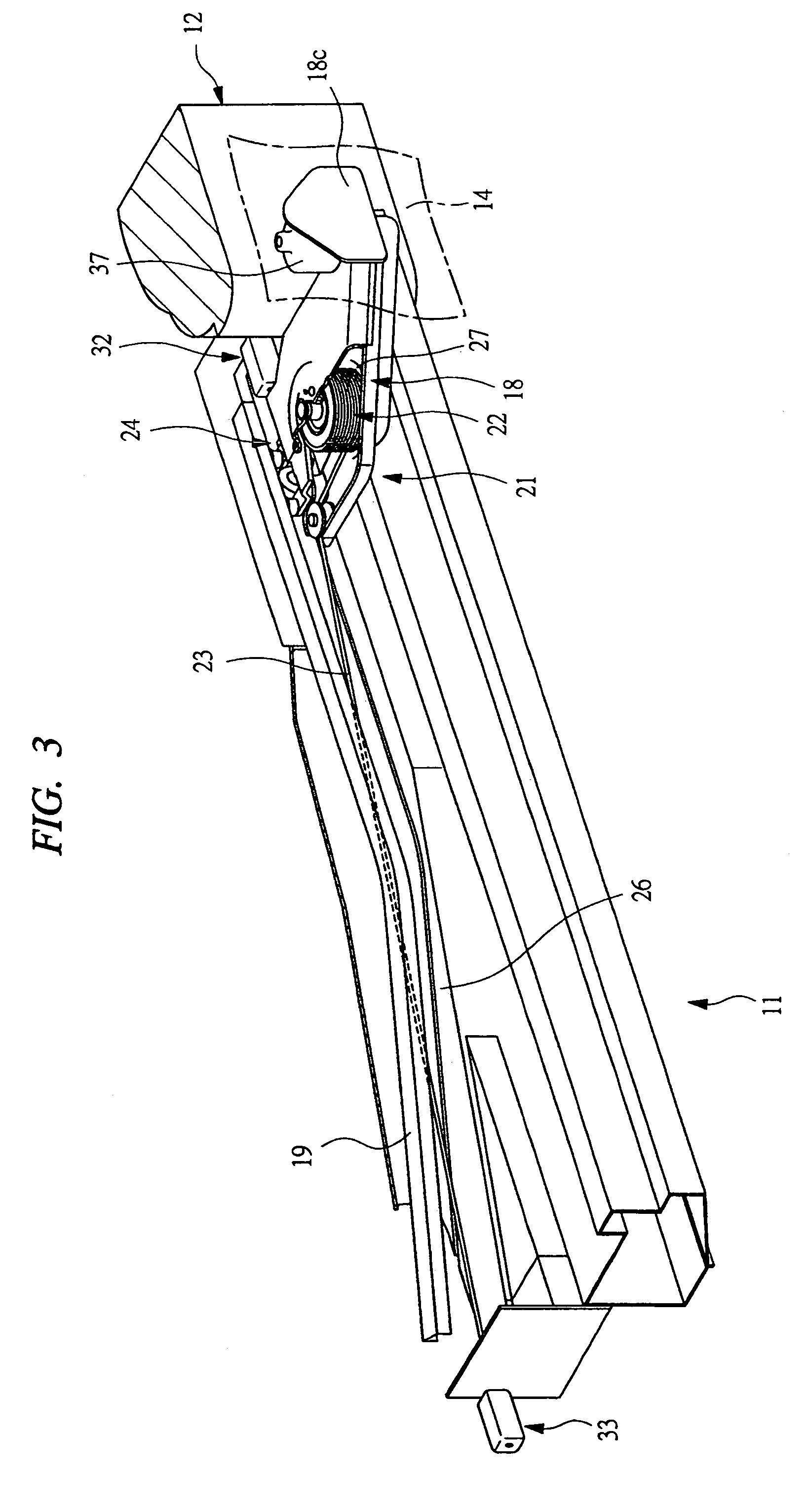
The present invention is a sliding door opening and closing device for vehicles that improves the layout flexibility of the driving unit and protects the cable member from interference and exposure. The device includes a guide rail fixed to the vehicle body, an arm member fixed to the sliding door and guided along the guide rail, a cable member with one end fixed to the vehicle body and the other end fixed to the sliding door, and a driving unit with a rotating member and a driving source for driving the sliding door. The driving unit is incorporated inside the arm member, which is fixed to the sliding door and guided along the guide rail. The ends of the cable member are fixed to the vehicle body through tension generators, and the guide rail is fixed to the lower edge of the platform and the arm member. This design prevents interference with other devices in the sliding door and improves the appearance of the vehicle. The arm member is downsized and made thinner, which decreases the height of the floor of the vehicle body.

Problems solved by technology

However, if the driving unit is incorporated inside the sliding door as in the conventional opening and closing device, dimensions and mounting positions of the respective devices are restricted in order to prevent the driving unit from interfering with a power window device, a locking mechanism, or the like located inside the sliding door and from getting wet with rain or the like, whereby layout flexibility decreases and design costs increase.

Method used


Image

  • Sliding door opening and closing device
  • Sliding door opening and closing device
  • Sliding door opening and closing device

Examples


Embodiment Construction

[0026]Embodiments of the present invention will be described in detail below based on the drawings.

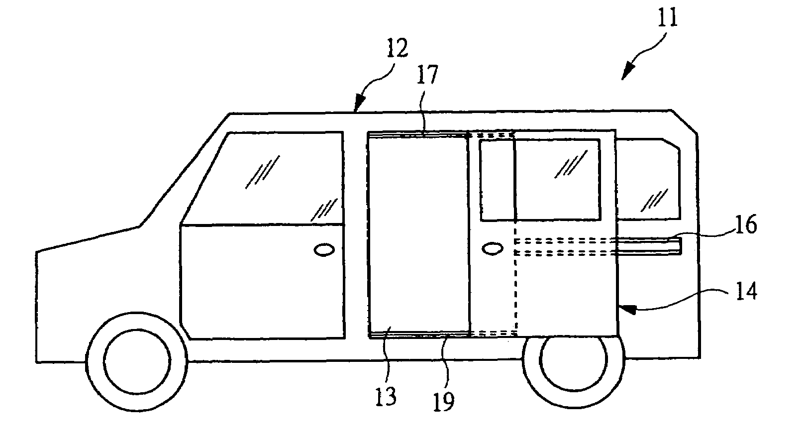
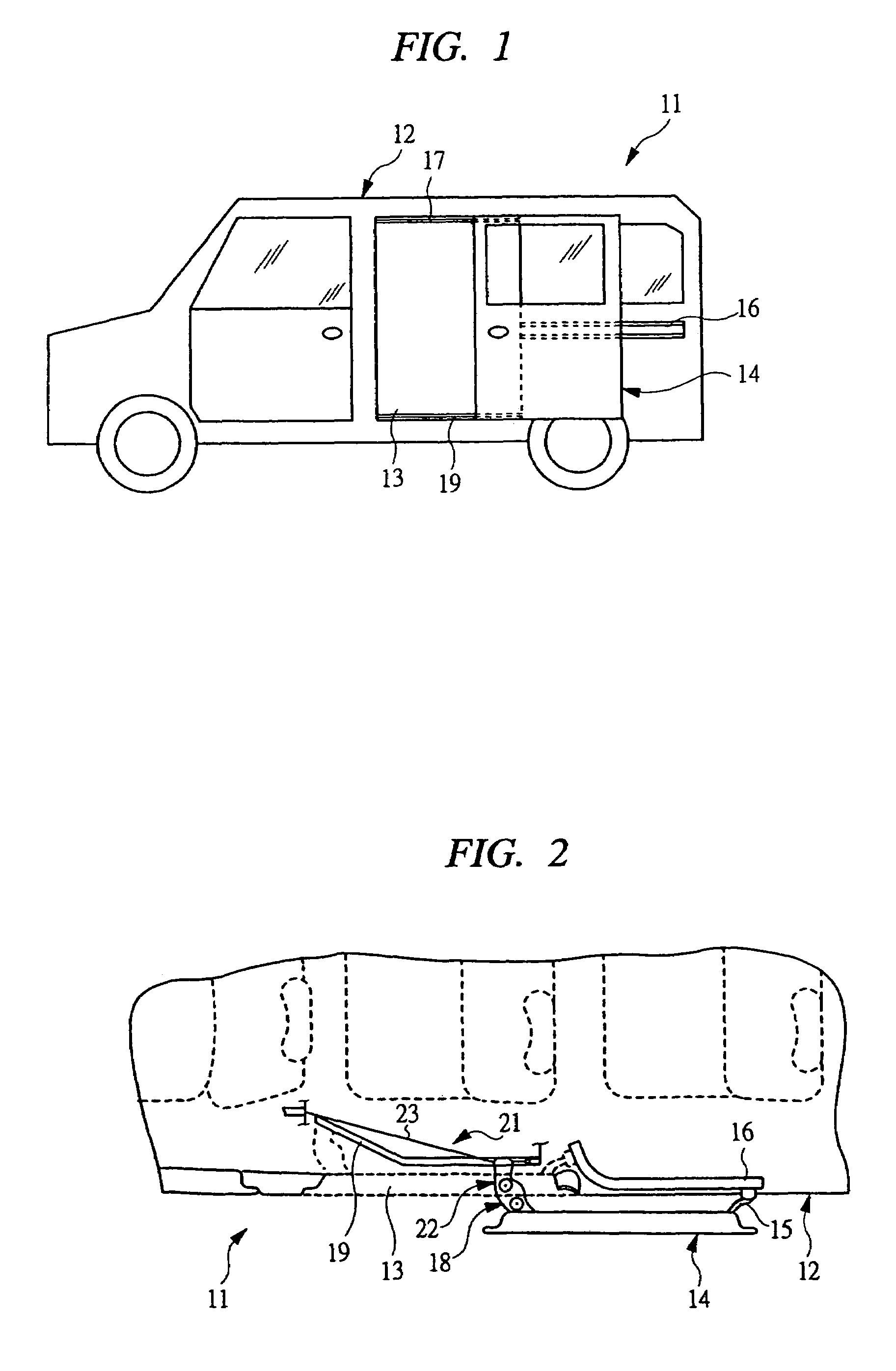
[0027]FIG. 1 is a schematic side view of a vehicle equipped with a sliding door opening and closing device according to an embodiment of the present invention. This vehicle 11 is provided with a sliding door 14 for opening and closing a platform 13 provided at a side of a vehicle body 12.

[0028]FIG. 2 is a view for explaining a configuration of attaching the sliding door shown in FIG. 1 to the vehicle. A center arm 15 is fixed to an end on a vehicle-rear side of the sliding door 14, and a center rail 16 is fixed on a vehicle-rear side of the platform 13 so as to be positioned at a substantially intermediated portion in a vehicle-vertical direction. Therefore, the center arm 15 is guided along the center rail 16 so as to be movable in a vertical-longitudinal direction. Also, an unshown upper arm is fixed to the vehicle-front side of the sliding door 14 so as to be positioned at an upper ...


PUM


Abstract

There is provided a sliding door opening and closing device that improves layout flexibility of a driving unit in a self-propelled sliding door opening and closing device in which the driving unit is disposed on a sliding door side and that can protect a cable member without adding a component such as a decorative sheet. A lower rail is fixed to the vehicle body, and a lower arm guided along the lower rail is fixed to the sliding door. A driving unit for driving the sliding door for opening and closing has a drum driven by an electric motor for rotation. A cable is wound around the drum, wherein one end of the cable is fixed to the vehicle body on a vehicle-front side of the lower rail and the other end thereof is fixed to the vehicle body on a vehicle-rear side of the lower rail. This driving unit is incorporated inside the lower arm so as to be integrally formed with the lower arm.

Description

CROSS-REFERENCE TO RELATED APPLICATIONS[0001]Applicant hereby claims foreign priority benefits under U.S.C. § 119 from Japanese Patent Application No. 2005-178532 filed on Jun. 17, 2005, the contents of which are incorporated by reference herein.BACKGROUND OF THE INVENTION[0002]The present invention relates to a sliding door opening and closing device for automatically opening and closing a sliding door provided at a platform of a side of a vehicle body.[0003]In wagon-type or minivan-type vehicles, a sliding door is often used as a door that opens and closes the platform provided at the side of the vehicle body. For such a sliding door, an upper arm and a lower arm provided with roller assemblies are fixed to an upper end and a lower end on a vehicle-front side, respectively. At an end on a vehicle-rear side, a center arm provided with a roller assembly is fixed. On the vehicle body, an upper rail and a lower rail are fixed so as to be positioned at an upper edge and a lower edge of...

Claims


Application Information

Patent Timeline
Patent Type & Authority Patents(United States)
IPC IPC(8): B60J5/06E05F15/632E05F15/643E05F15/655
CPCE05F15/646E05D2015/1055E05Y2201/434E05Y2900/531E05Y2600/46
Inventor SATO, MASAEI
Owner MITSUBA CORP
Learn More