Catalyst system for lean burn engines

a technology of catalyst system and burn engine, which is applied in the direction of physical/chemical process catalyst, metal/metal-oxide/metal-hydroxide catalyst, separation process, etc., can solve the problems of increasing the difficulty of treating some polluting gases, developing a lean bias, and high cost of catalyst manufacture, so as to eliminate nox release and increase thermal stability and light-off

Inactive Publication Date: 2008-02-12
FORD GLOBAL TECH LLC
View PDF23 Cites 56 Cited by
  • Summary
  • Abstract
  • Description
  • Claims
  • Application Information

AI Technical Summary

Benefits of technology

[0020]We have found that a catalyst system of this construction and composition is capable of oxidizing hydrocarbons and carbon monoxide while also storing NOx under lean conditions. This catalyst system further provides for the combined treatment of emissions from engines operating under stoichiometric and lean burn conditions, provides increased thermal stability and light-off for the catalyst and eliminates the NOx release associated with lean NOx traps. This and other aspects of the invention will be described in detail below.

Problems solved by technology

Because of the high cost of the precious metals, these catalysts are expensive to manufacture.
While lean operation improves fuel economy, operating under lean conditions increases the difficulty of treating some polluting gases, especially NOx.
HEGO sensors, however, over time can develop a lean bias as a result of poisoning.
However, in addition to problems associated with thermal stability and sulfur tolerance, lean NOx traps have the following two known problems: (1) a problem referred to as “NOx release”, the release of unreduced NOx from the NOx trap during the transition from lean to rich conditions; and (2) a reduction in fuel economy that results from frequent purges of the NOx trap. FIG. 2 shows the NOx release for a catalyst with different oxygen storage capacities (“OSC”).
With regard to the fuel economy penalty, this is believed to be the result of high oxygen storage capacity (OSC), low NOx trapping capacity, and / or high exhaust flow rate in the lean NOx trap.
While this layering approach enhances the ability of the platinum to reduce exhaust emissions under stoichiometric conditions, it does not sufficiently reduce NOx emissions under prolonged lean engine conditions.

Method used


Image

  • Catalyst system for lean burn engines
  • Catalyst system for lean burn engines
  • Catalyst system for lean burn engines

Examples


example 1

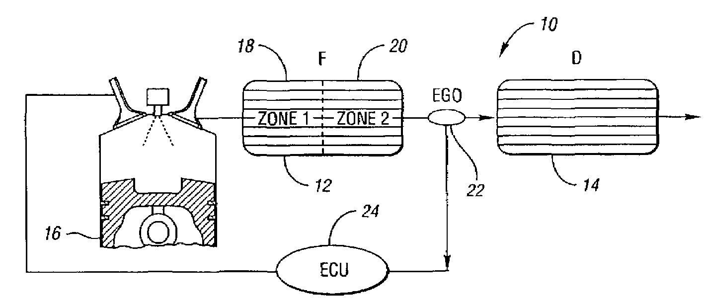
[0054]Fumed alumina Al2O3 (15 g, Degussa), Ba(NO3)2 (7.42 g), KNO3 (0.3 g), La (NO3)3.6H2O(20.3 g), and H2PtCl6.6H2O (1.48 g) are each added to 500 ml deionized water, heated to 60° C., and then mixed as solution 1 with the final desired ratios. A rhodium solution containing 0.10 g Rh(NO3)4 is deposited onto 2.6 g ZrO2, dried at 80 E C for eight hours and then calcined at 600° C. for six hours. The resulting powder is crushed and added to solution 1. Meanwhile, fumed alumina Al2O3 (15 g, Degussa), Ba(NO3)2 (14.84 g), and Rh(NO3)4 (0.1 g), and H2PtCl6.6H2O (0.23 g) are each added to 500 ml deionized water, heated to 60° C., and then mixed as solution 2 with the final desired ratios. The top half of a core of 400 cell per square inch cordierite (2 inch in diameter and 3.25 inch in length, zone 1) was dipped into solution 1, and then dried at 80° C. overnight. This process was repeated until the desired amount of mixed compound was coated on the core. The bottom half of the core (zone ...

example 2

[0055]This is a comparative example of a conventional lean NOx trap. Fumed alumina (50.0 g, Degussa), and Ba(NO3)2 (17.13 g) are dissolved in 500 ml deionized water. This mixture is stirred on a hot plate for 1 hour, and then dried at 80° C. overnight, and then calcined at 600° C. for 6 hours. The calcined powder is ground with 2.5 g Ce / Zr mixed oxide (W.R. Grace) for 48 hr in 100 ml deionized water. Then it is dried at 80° C. overnight, and calcined at 600° C. for 6 hours. This powder is then mixed with H2PtCl6.6H2O in 2.65 g deionized water, ground for 24 hour, then dried at 80° C. and calcined at 600° C. for 6 hr.

example 3

[0056]This example shows the test procedures and conditions. The steady state lean NOx trapping efficiency was measured in a flow reactor as an average efficiency during a 1 minute lean period under different temperatures. The feedgas cycled with 60 seconds lean and 5 seconds rich at a constant space velocity of 30,000 hour−1. The flow rates were strictly controlled by mass flow controllers. The gas concentrations were measured by a V&F mass spectrometer. The feedgas composition was:

[0057]

GasesConcentration (lean)Concentration (rich)NO 500 ppm 500 ppmHC1500 ppm1500 ppmCO0  4%H201.33%O2 6%0CO210%  10%H2O10%  10%N2balancebalance

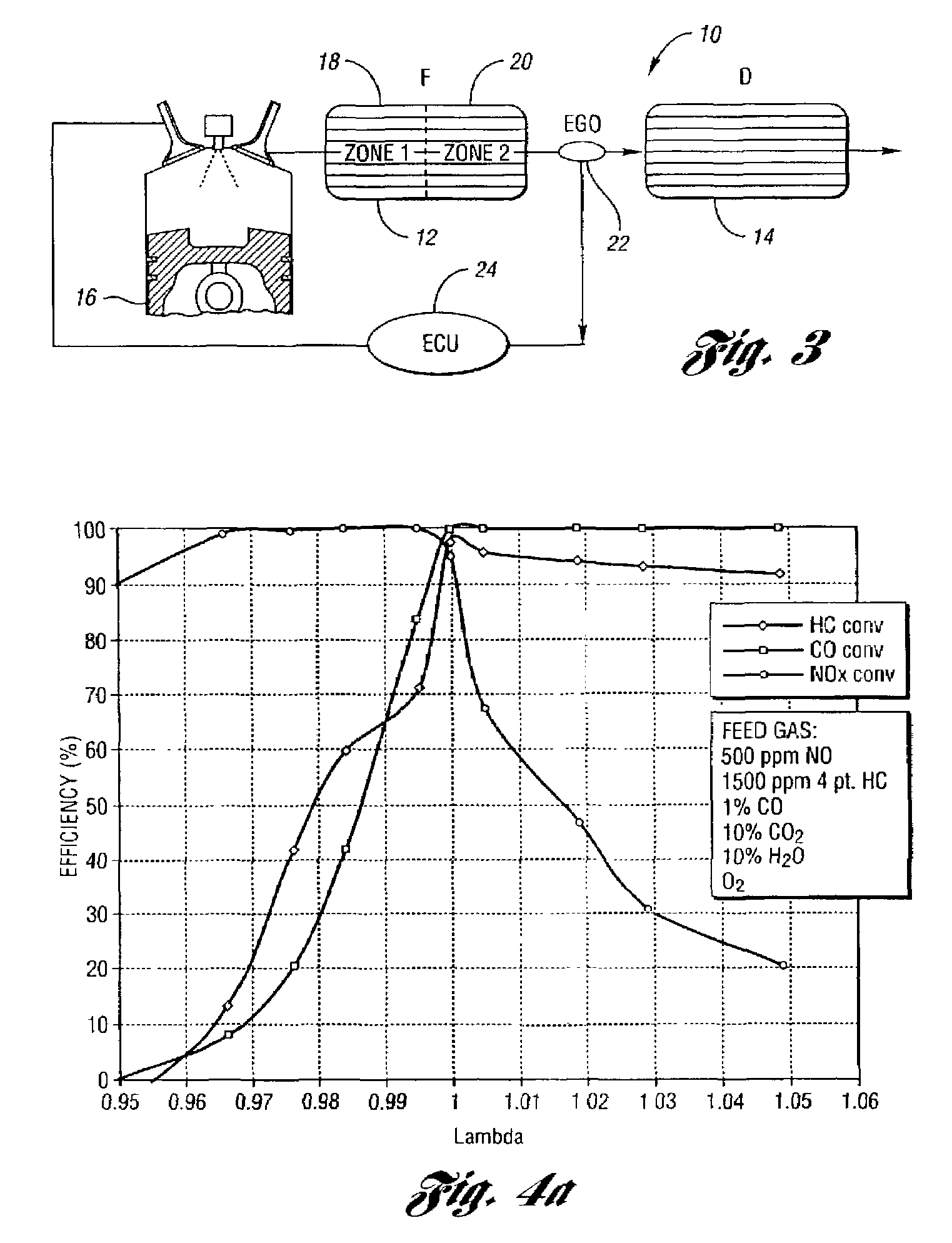
[0058]The lambda sweep tests were also conducted in a flow reactor at 400° C. with a gas space velocity of 30,000 hour−1. Here the feedgas composition remains constant except the oxygen concentration varies to achieve the desired lambda value. The feedgas contains 2000 ppm HC, 500 ppm NO, 1% CO, 0.33% H2, 10% CO2, 10% H2O, and N2 balance.

[0059]Catalyst aging is...


PUM

PropertyMeasurementUnit
exothermic temperatureaaaaaaaaaa
operating temperaturesaaaaaaaaaa
temperatureaaaaaaaaaa

Abstract

A catalyst system to provide emission reductions under lean and stoichiometric conditions. The catalyst system comprises a forward catalyst having a first cerium-free zone including oxides of aluminum, alkali metals and alkaline earth metals and precious metals and a second zone with a lower loading of precious metals, oxides of aluminum, alkali metals or alkaline earth metals. This forward catalyst stores NOx emissions under lean conditions for subsequent reduction and converts HC, CO and NOx during stoichiometric operation. The second downstream catalyst includes precious metals, reduces emissions under stoichiometric conditions, and stores any residual NOx emitted from the first catalyst for subsequent reduction. In another embodiment, a forward catalyst has top and bottom layers designed to reduce emissions under lean conditions. In this embodiment, a second downstream catalyst is used to reduce emissions under stoichiometric conditions. In yet another catalyst, multiple zones are created within a single catalyst.

Description

BACKGROUND OF INVENTION[0001]1. Field of the Invention[0002]The present invention is directed to a catalyst system for use with internal combustion engines to oxidize hydrocarbons, carbon monoxide and reduce nitrogen oxides in an exhaust gas when the engine is operated at both lean and stoichiometric air / fuel ratios. More particularly, the catalyst system of this invention includes two catalysts. One of the catalysts is designed specifically to store NOx emissions under lean conditions and reduce the stored NOx during rich operation. Additionally, this catalyst also serves to convert HC, CO and NOx during stoichiometric operation. This catalyst consists of two zones—a cerium-free zone containing aluminum oxide, oxides of alkali metals, alkaline earth metals and a high loading of precious metals, and a second zone of oxides of aluminum, alkali metals, alkaline earth metals, rare earth metals, or combinations thereof, and a lower loading of precious metals. The first catalyst can also...

Claims


Application Information

Patent Timeline
Patent Type & Authority Patents(United States)
IPC IPC(8): B01J23/00B01D53/94B01J23/58B01J23/63B01J23/89B01J35/00B01J37/02
CPCB01D53/945B01J23/58B01J23/63B01J35/0006B01J37/0244B01J23/892B01J37/0248Y02T10/22Y02T10/12
Inventor GANDHI, HAREN SLI, JUN JOHNTHEIS, JOSEPH ROBERTHURLEY, RONALD GENEWATKINS, WILLIAM LEWIS HENDERSON
Owner FORD GLOBAL TECH LLC
Why Eureka
Try Eureka