

Discharge lamp, method for fabricating the same and lamp unit
a discharge lamp and lamp unit technology, applied in the manufacture of electric discharge tubes/lamps, cold cathode manufacturing, electrode systems, etc., can solve the problems of short lamp life and deterioration of mo foil
- Summary
- Abstract
- Description
- Claims
- Application Information
AI Technical Summary
Benefits of technology
Problems solved by technology
Method used
Image

Examples
embodiment 1
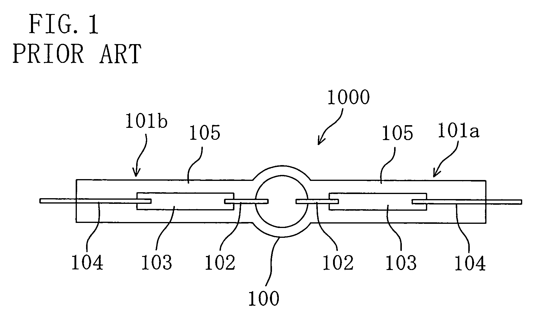
[0091]A discharge lamp 50 according to a first embodiment of the present invention will be described with reference to FIG. 4. FIG. 4 schematically illustrates the structure of the discharge lamp 50 according to this embodiment.
[0092]The discharge lamp 50 shown in FIG. 4 includes a luminous bulb (bulb) 10 and sealing parts 11a and 11b coupled to both ends of the luminous bulb 10. The sealing parts 11a and 11b are members for holding the hermiticity of the inside of the luminous bulb 10. The discharge lamp 50 is a double-ended lamp comprising two sealing parts. A luminous material 18 is encapsulated in the luminous bulb 10. A pair of electrodes 12 are arranged so as to be opposed to each other. Metal foil structures 13 are electrically connected to the pair of electrodes, respectively. The metal foil structure 13 located in the sealing part 11a consists of a metal foil (molybdenum foil). Outer leads 14 are electrically connected to parts of the metal foil structures 13 opposite to th...
embodiment 2
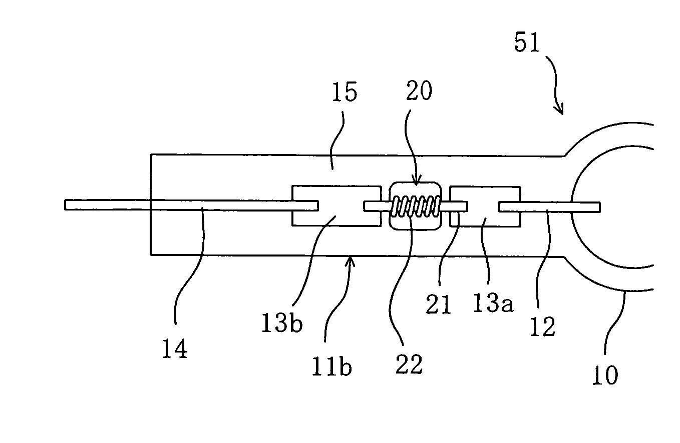
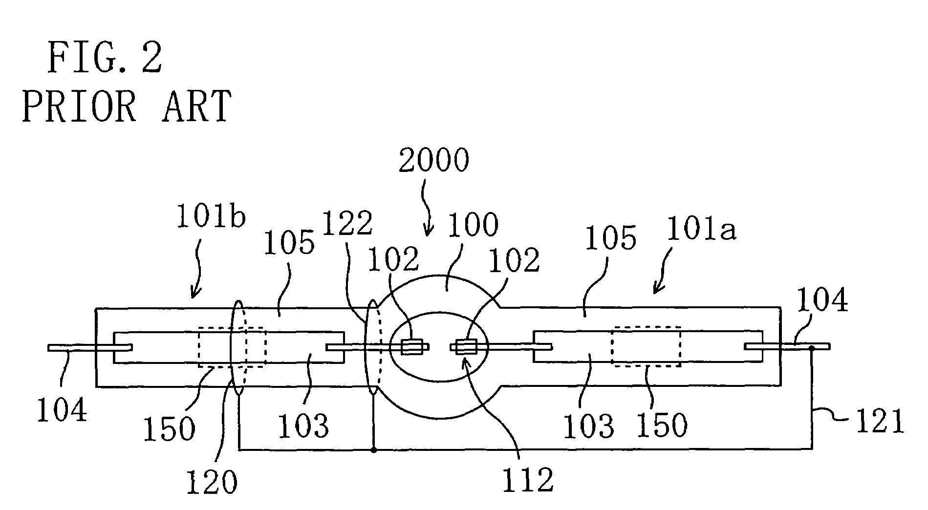
[0121]Next, a discharge lamp according to a second embodiment of the present invention will be described with reference to FIG. 10. FIG. 10 schematically illustrates the structure of a sealing part 11b of a discharge lamp 51 according to the second embodiment.
[0122]The discharge lamp 51 shown in FIG. 10 is constructed such that a coil 22 is wound around a metal bar 21 of the discharge lamp 50 according to the above embodiment.
[0123]The other points are the same as in the structure of the above embodiment. Therefore, for the sake of simplicity, the descriptions are omitted or simplified with respect to the same contents.
[0124]With the structure of the lamp according to this embodiment, a coil 22 made of thoriated tungsten is wound around a metal bar 21, thereby facilitating the discharge between an antenna and the coil 22 or metal bar 21. The coil 22 may be made of tungsten. One obtained by applying thoriated tungsten to the coil made of tungsten may be used as the coil 22. In this e...
embodiment 3
[0144]Each of the high-pressure discharge lamps of the above first and second embodiments can become a mirror-mounted lamp or a lamp unit in combination with a reflecting mirror.
[0145]FIG. 17 schematically illustrates the cross section of a mirror-mounted lamp 900 comprising the lamp 50 of the above first embodiment. The cross section is not hatched.
[0146]The mirror-mounted lamp 900 is composed of a lamp 50 and a reflecting mirror 200 for reflecting light emitted from the lamp 50. An antenna (not shown) is provided around the cavity 20 of the lamp 50. The lamp 50 is shown as an example, and thus the lamp 51 or 52 of the above embodiments may be used instead. The mirror-mounted lamp 900 may further comprise a lamphouse for holding a reflecting mirror 200. Here, the structure of the mirror-mounted lamp 900 comprising a lamphouse is included in a lamp unit.
[0147]The reflecting mirror 200 is made of heat-resistant glass whose inside surface is partly composed of a parabolic body, and a ...
PUM
| Property | Measurement | Unit |
|---|---|---|
| voltage | aaaaa | aaaaa |
| open-circuit voltage | aaaaa | aaaaa |
| open-circuit voltage | aaaaa | aaaaa |
Abstract
Description
Claims
Application Information