Light-redirecting optical structures

a technology of optical structures and lenses, applied in the direction of instruments, lighting and heating apparatus, mechanical apparatus, etc., can solve the problems of optical film “wetting out”, defects that are often noticeable by the viewer, and defects in the lighting panel

Inactive Publication Date: 2008-02-12
ORAFOL AMERICAS +1
View PDF108 Cites 29 Cited by
  • Summary
  • Abstract
  • Description
  • Claims
  • Application Information

AI Technical Summary

Benefits of technology

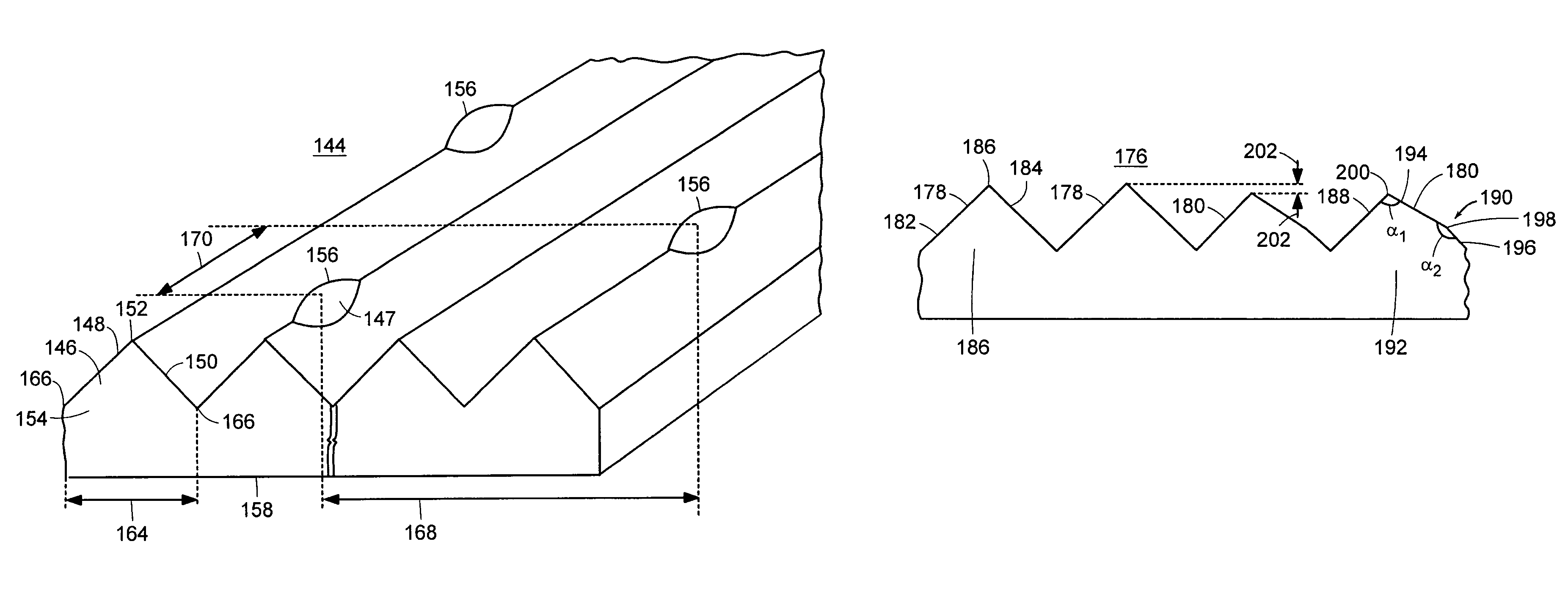
[0014]In yet other embodiments, an optical structure is provided that includes an optical layer and a plurality of microstructures, each having at least a first side and a second side terminating at a peak, with peaks of the prisms being spaced sufficiently away from the optical layer to prevent or minimize an undesirable optical condition, such as wet-out. The optical layer can include a diffuser.
[0017]The optical structure can further include a second plurality of microstructures having a base, a first side, and a second side, with the first side including a first planar surface, and the second side including a second planar surface and a third planar surface. The peaks of the first plurality of microstructures extend above peaks of the second plurality of microstructures to space peaks of the second plurality of microstructures away from the optical layer to prevent or minimize an undesirable optical condition, such as wet-out.

Problems solved by technology

When the optical films are positioned adjacent another layer, such as a diffuser or another optical film, defects in the lighting panel are often noticeable by the viewer.
One such defect is caused by the optical film “wetting-out”, which can occur when the film contacts an adjacent film.
Since the two films are not uniformly contacting one another, defects are noticeable by the viewer.

Method used


Image

  • Light-redirecting optical structures
  • Light-redirecting optical structures
  • Light-redirecting optical structures

Examples


Embodiment Construction

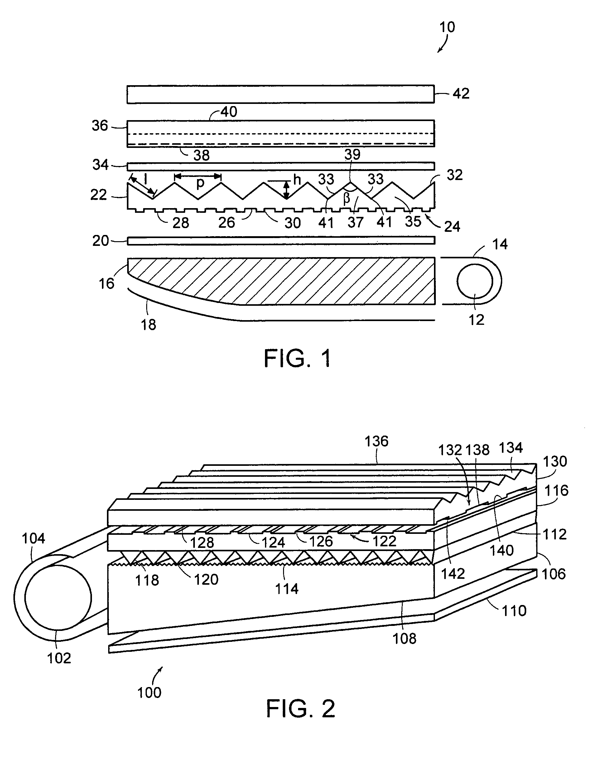
[0033]A description of various embodiments of the invention follows. Often, the term optical “sheets” refers to a more rigid substrate, for example, one that could be leaned against a wall without folding over on itself, and the term optical “films” refers to a substrate that is more flexible, for example, one that could be rolled up. However, depending on the size and thickness of the sample, a film can act as a sheet. For example, a small, thin polyester film can be rigid enough to lean against a wall without folding over on itself. For purposes of understanding aspects of the present invention, the terms “sheet” and “film” can be used interchangeably. Sheets and films of the present invention can be formed from plastic material, such as, polyurethane, polypropylene, polyvinyl chloride, polycarbonate, polyester, polyurea, or polymethylmethacrylate. Polyurea is disclosed in U.S. Provisional Application No. 60 / 402,484, filed on Aug. 8, 2002, and U.S. patent application Ser. No. 10 / 6...


PUM


Abstract

A plurality of microstructures is provided, with each microstructure having at least a first side and at least a second side terminating at a peak. At least some of the peaks can include an elevated portion to space the peaks away from adjacent optical sheets, surfaces, films, substrates, or other layers to minimize wet-out, Newton's rings, abrasions, moiré fringes, or other undesirable optical conditions. In other embodiments, an optical film is also provided that includes a first plurality of microstructures having a base, a first side, and a second side, and a second plurality of microstructures having a base, a first side, and a second side, the first side including a first planar surface, and the second side including a second planar surface and a third planar surface.

Description

RELATED APPLICATION[0001]This application claims the benefit of U.S. Provisional Application No. 60 / 467,494, filed May 2, 2003, the entire teachings of which are incorporated herein by reference.BACKGROUND OF THE INVENTION[0002]Brightness enhancing films (BEF) have been used in lighting panels for directing light from lighting fixtures through luminaires, laptop computers displays, and flat panel desk top monitors or displays. The brightness enhancing films, which can have linear prisms, diffuse light with a desired directionality. Often the films have been used in combination with a fluorescent light source. The films have had partial success in improving luminaire or display brightness by controlling the angle at which light emerges.[0003]Optical films are often used in combination with other films or sheets. For example, two diffuse films and two light-redirecting or collimating films are used as a stack on a light guide behind liquid crystal displays. When the optical films are ...

Claims


Application Information

Patent Timeline
Patent Type & Authority Patents(United States)
IPC IPC(8): G02B27/10F21V8/00G02B5/04
CPCG02B6/0053G02B5/045
Inventor NILSEN, ROBERT B.
Owner ORAFOL AMERICAS
Why Eureka
Try Eureka