
Method for video transcoding with adaptive frame rate control

a frame rate control and adaptive technology, applied in the field of transcoders, can solve the problems of low complexity of tb>1/b> transcoder, primary loss in mpeg standards, and the space for novelty and variety of the algorithm employed in the encoder, and achieve good temporal-spatial quality tradeoff

Active Publication Date: 2008-02-12
IBM CORP
View PDF8 Cites 85 Cited by
  • Summary
  • Abstract
  • Description
  • Claims
  • Application Information

AI Technical Summary

Benefits of technology

The present invention provides a video transcoding method with an adaptive frame rate and joint temporal-spatial rate control technique. This method can significantly enhance the quality of compressed MPEG video by controlling the transcoding in both the temporal and spatial domains. The method is efficient and can be used for transcoding high bit rate video to lower bit rate video, as well as for real-time applications. The joint temporal-spatial rate control method adjusts both the picture or frame rate and the picture or frame quantization step size simultaneously according to the channel bandwidth to achieve a good temporal-spatial quality tradeoff. The described MPEG-2 to MPEG-4 video transcoder with adaptive frame rate and joint temporal-spatial rate control can out-perform the prior art transcoding methods that transcode with constant frame rate.

Problems solved by technology

The MPEG standards define the syntax of the compressed bit stream and the method of decoding, but leave considerable space for novelty and variety in the algorithm employed in the encoder.
The second step, quantization of the DCT coefficients, is the primary source of loss in the MPEG standards.
Consequently, the complexity of the T1 transcoder is very low.
However, drift errors can occur in P and B frames and accumulate in P frames until the next I frame is transcoded.
Thus, the quality of T1 is poor.
However, this results in a very high computational complexity, and T3 is not suitable for low complexity or real-time applications.
However, both of them tried to control the bit rate at a constant frame rate, i.e. frame skipping was not adopted.

Method used


Image

  • Method for video transcoding with adaptive frame rate control
  • Method for video transcoding with adaptive frame rate control
  • Method for video transcoding with adaptive frame rate control

Examples


Embodiment Construction

Spatial Resolution and Motion Vector Down-Sampling Processes in Transcoding

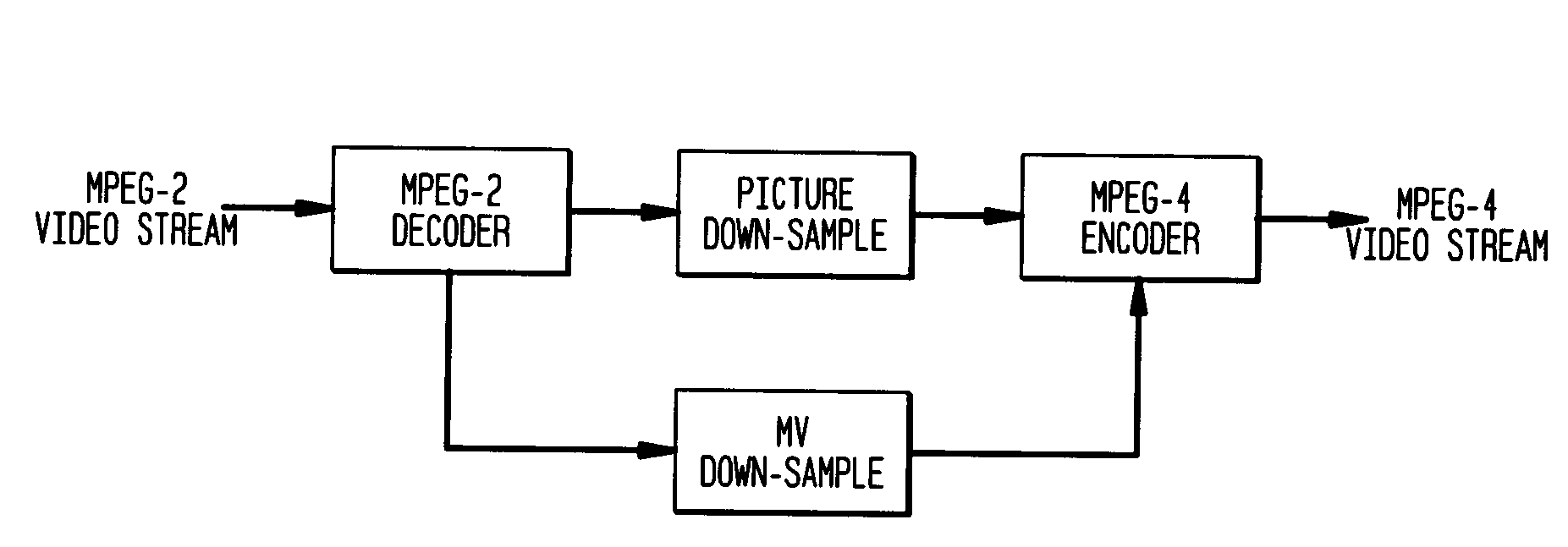
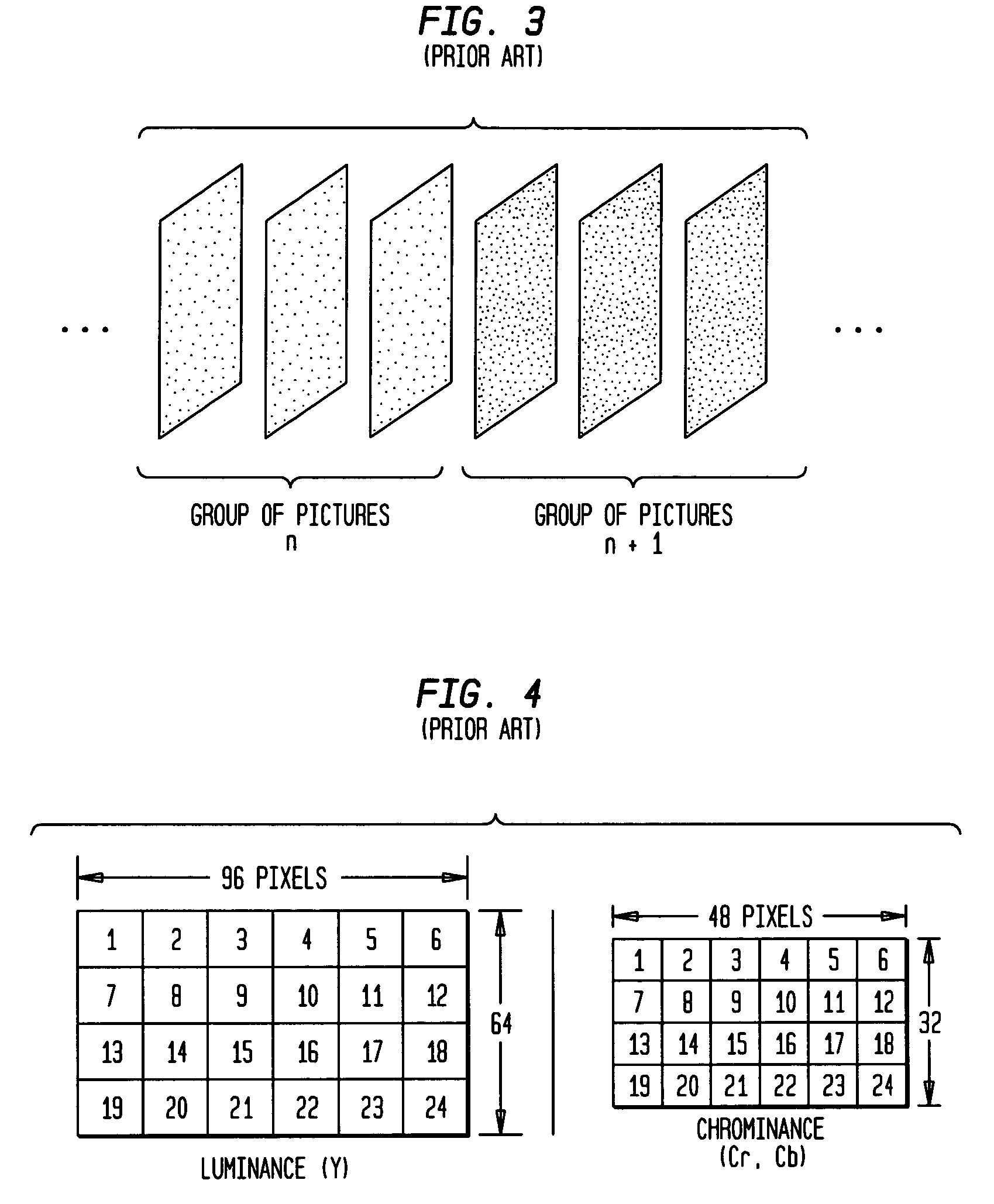
[0059]Without loss of generality, consider the case of spatial resolution down-sampling shown broadly in FIG. 10 where the input is MPEG-2 video with a higher spatial resolution, (e.g. CIF (Common Intermediate Format) resolution 352×288, 4 CIF resolution 704×576, or 4 SIF (Source Input Format) resolution 720×480) while the output is MPEG-4 video with a lower resolution (e.g. CIF resolution 352×288 or QCIF (Quarter CIF) resolution 176×144). Hence, the MPEG-2 frame picture has to be down-sampled to fit the MPEG-4 image size, which is a typical case. The T2 transcoder is adopted so that the resolution down-sampling can be processed in the pixel domain. As shown in FIG. 4, the MPEG-2 video is down-sampled with 2:1 ratio in both vertical and horizontal directions so that the QCIF MPEG-4 frame image can be obtained.

[0060]FIG. 11(a) is a block diagram of a preferred embodiment of a transcoder pursuant to the present...


PUM


Abstract

A video transcoding method is provided for transcoding a first signal stream compressed by a first coding scheme to a second signal stream compressed by a second coding scheme. The method employs an adaptive frame rate and a joint temporal-spatial rate control technique, such that the overall quality of compressed MPEG video can be significantly enhanced when the transcoding is controlled in the joint temporal (picture or frame rate) and spatial (quantization) domains. One embodiment considers transcoding from high bit rate video with larger image size (e.g. 4CIF / 4SIF, CIF) coded by one coding technique, e.g., MPEG-2 to a lower bit rate video with smaller image size (e.g. CIF, QCIF) coded by the same or another coding technique, e.g., MPEG-4.

Description

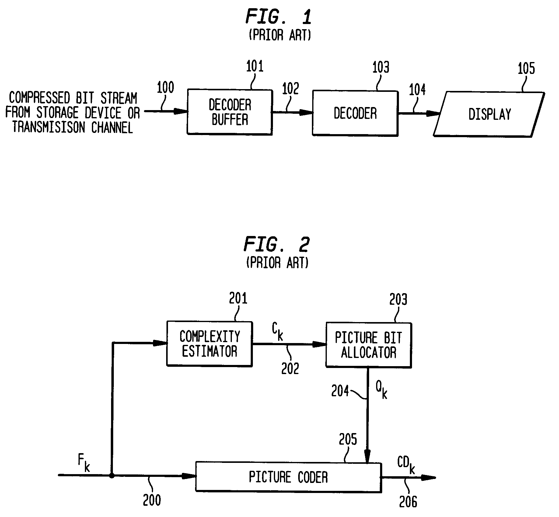
BACKGROUND OF THE INVENTION[0001]1. Field of the Invention[0002]The present invention relates generally to transcoders for converting or transcoding a first signal stream compressed by a first coding scheme to a second signal stream compressed by a second coding scheme. The subject invention is particularly suitable for transcoding compressed digital video streams such as MPEG video streams.[0003]2. Discussion of the Prior Art[0004]FIG. 1 is a diagram of a conventional prior art Virtual Buffer Verifier wherein a compressed bit stream from a storage device or transmission channel at 100 is input to a decoder buffer 101 which is connected over a communication link 102 to a decoder 103, the output of which at 104 is displayed at 105.[0005]FIG. 2 is an overview of a conventional prior art video compression system wherein an input video stream Fk at 200 is directed as a first input to a picture coder 205 and as an input to a complexity estimator 201. The complexity estimator output estim...

Claims


Application Information

Patent Timeline
Patent Type & Authority Patents(United States)
IPC IPC(8): H04N7/12G06K9/36H04N7/26
CPCH04N19/40
Inventor LU, LIGANGLIU, SHAN
Owner IBM CORP
Learn More