
Method and system for extracting data from surface array deposited features

a technology of surface arrays and features, applied in image analysis, image enhancement, instruments, etc., can solve the problems of noise, variation, and deviation of scan images of molecular array features, and achieve the effect of reducing the number of scan images

Inactive Publication Date: 2008-02-12
AGILENT TECH INC
View PDF15 Cites 19 Cited by
  • Summary
  • Abstract
  • Description
  • Claims
  • Application Information

AI Technical Summary

Benefits of technology

[0009]In one aspect, a method is provided for evaluating an actual orientation of a molecular array having features which may be arranged in a pattern (for example, on a rectilinear grid). In this method, one or more images of the molecular array are obtained. Such images may be produced by scanning the molecular array to determine data signals emanating from discrete positions on a surface of the molecular array, or by other means. An actual result of a function is calculated on positions (for example, pixels) of an image, which positions lie in a second pattern (for example, along one or more paths such as along the expected positions of array features). This actual result is compared with an expected result which would be obtained if the second pattern had a predetermined orientation on the array (for example, superimposed over at least part of the array). An actual array orientation may be evaluated based upon the results of the comparison. For example, if there is more than a predetermined difference (a “tolerance”) between the actual and expected results, this could be taken as an indication that the array does not have the expected orientation in a scanner. Before trying to interpret the image data further, the orientation of the second pattern on the array can be altered and the comparison step repeated, and these comparison and second pattern re-orientation steps repeated in further iterations as often as necessary until the actual and expected results are within the predetermined difference (at which point the actual and expected orientations should be the same, within the predetermined tolerance ). The greater the points on the second pattern, the greater the accuracy of the orientation information that can generally be obtained from the comparison.
[0013]It will also be appreciated throughout the present application that where steps are referenced as being implemented by a computer program, any such steps can also be implemented by hardware or hardware / software combinations which can perform the steps. Also, an “image” in relation to an array is a term which includes data on the position of the features regardless of how such data was obtained (for example, by scanning with a laser beam, or by some other means). Furthermore, wherever a function is referenced, this can for example be a summation. Likewise, wherever summation is referenced, other suitable functions might be used than a simple summation. For example, a weighted summation could be used at those locations on the second pattern which will be superimposed on reference marks or features with expected stronger signals. (such as control features) relative to other features, when the second pattern and array are superimposed. When reference marks are present, it will be appreciated that they can be detected and an orientation of the array (such as rotational orientation) can be evaluated based on the detected positions of the reference marks. For example, an approximate indication of array orientation can be based on the detected positions of the reference marks followed by further evaluating a refined array orientation using the above described comparison and re-orientation procedure, such that fewer iterations of the comparison and second pattern re-orientation procedure may be required.

Problems solved by technology

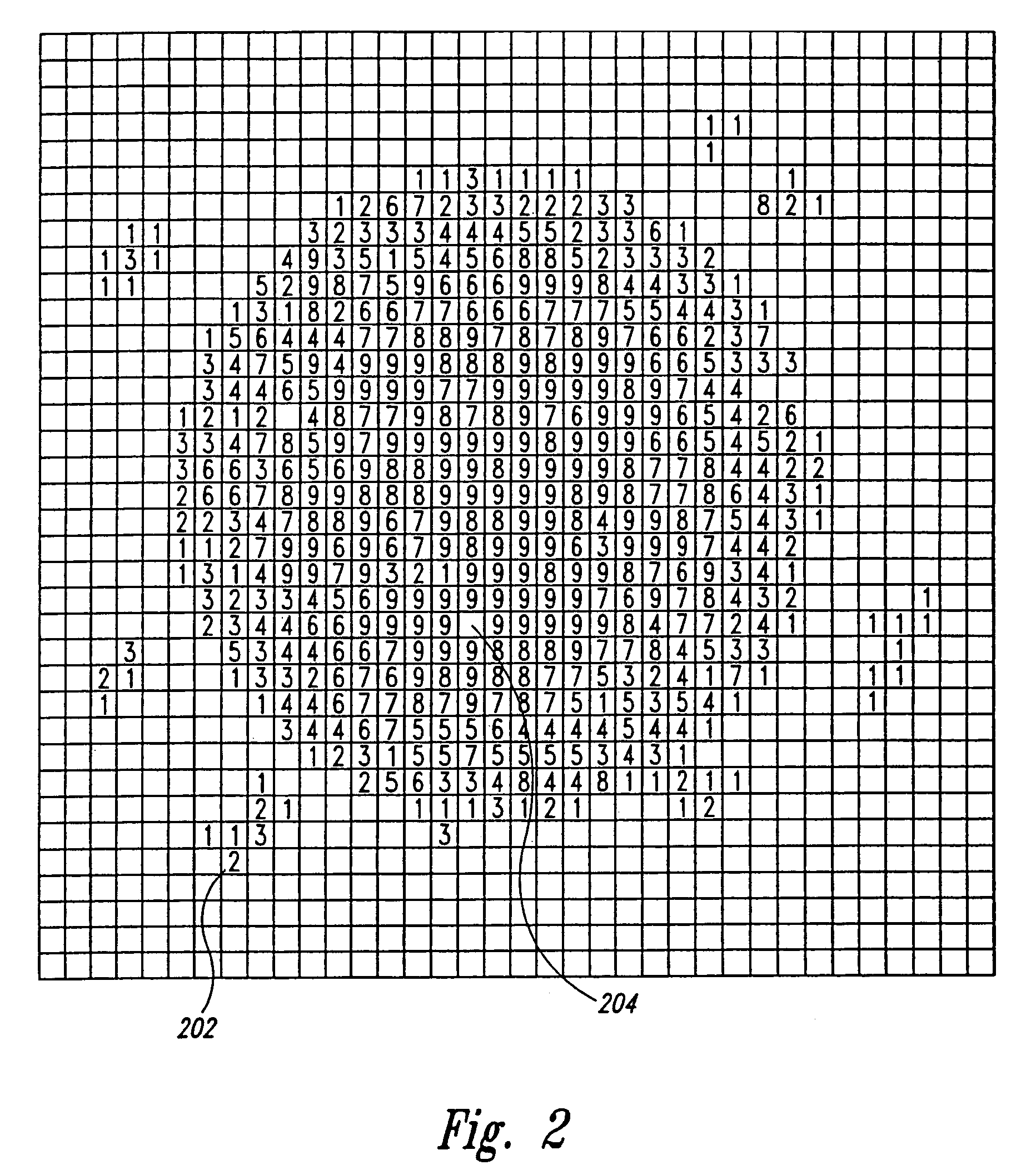
However, background signals, such as the background signal represented by non-zero pixel 202, may arise from non-specific binding of labeled molecules due to imprecision in preparation of molecular arrays and / or imprecision in the hybridization and washing of molecular arrays, and may also arise from imprecision in optical or radiometric scanning and various other sources of error that may depend on the type of analysis used to produce the scanned image.
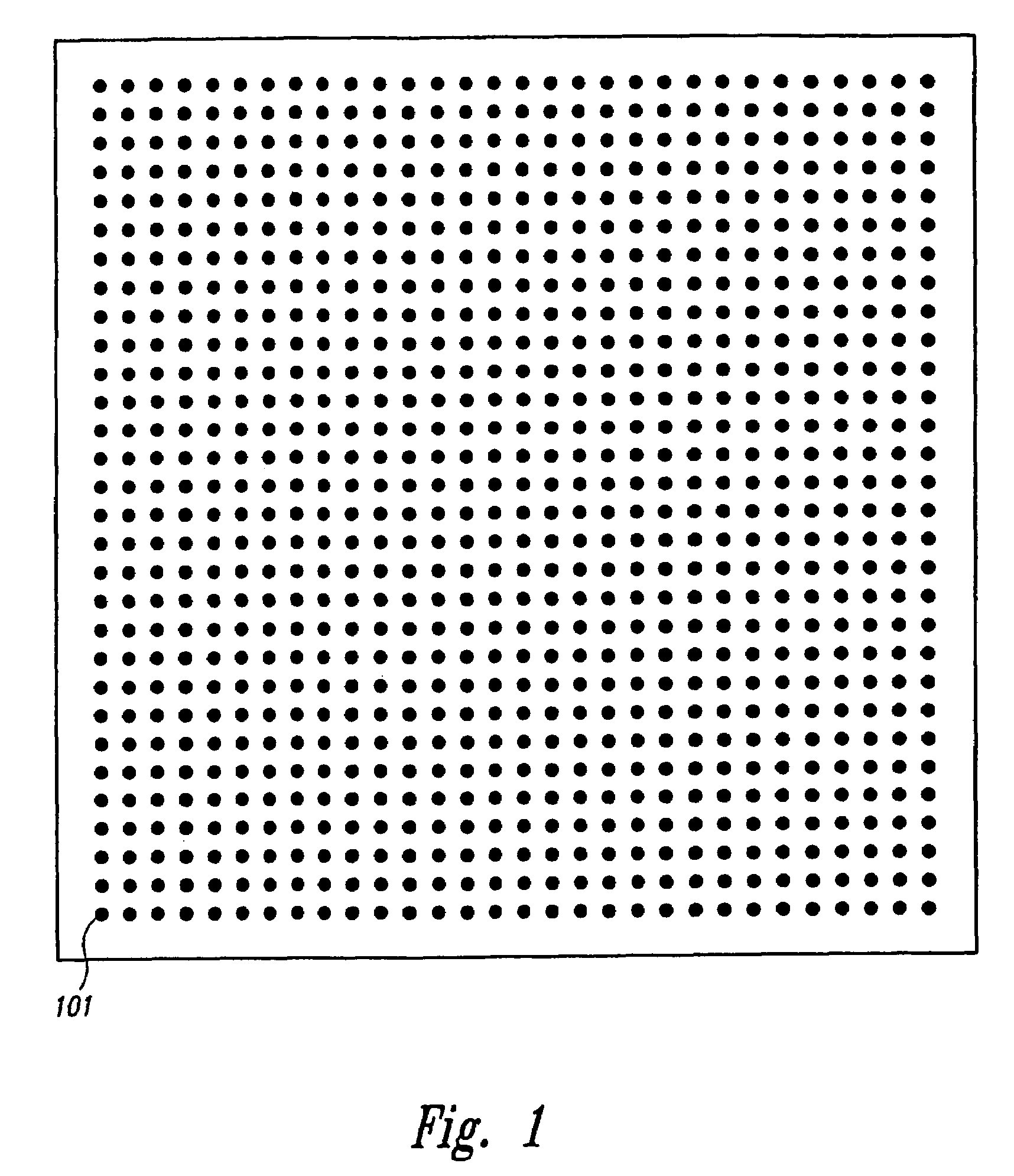
Thus, scanned images of molecular array features may often show noise and variation and may depart significantly from the idealized scanned image shown in FIG. 1.

Method used


Image

  • Method and system for extracting data from surface array deposited features
  • Method and system for extracting data from surface array deposited features
  • Method and system for extracting data from surface array deposited features

Examples


Embodiment Construction

[0055]When one item is indicated as being “remote” from another, this is referenced that the two items are at least in different buildings, and may be at least one mile, ten miles, or at least one hundred miles apart. “Communicating” information references transmitting the data representing that information over a suitable communication channel (for example, a private or public network). “Forwarding” an item refers to any means of getting that item from one location to the next, whether by physically transporting that item and includes, at least in the case of data, physically transporting a medium carrying the data or communicating the data. An array “package” may be the array plus only a substrate on which the array is deposited, although the package may include other features (such as a housing with a chamber). A “set” or a “sub-set” may have one or more members (for example, one or more features). Reference to a singular item, includes the possibility that there are plural of th...


PUM


Abstract

A method for evaluating an orientation of a molecular array having features arranged in a pattern. An image of the molecular array is obtained by scanning the molecular array to determine data signals emanating from discrete positions on a surface of the molecular array. An actual result of a function on pixels of the image which pixels lie in a second pattern, is calculated. This actual result is compared with an expected result which would be obtained if the second pattern had a predetermined orientation on the array. Array orientation can then be evaluated based on the result.

Description

CROSS-REFERENCE TO RELATED APPLICATIONS[0001]This application is a continuation of U.S. patent application Ser. No. 09 / 659,415, filed Sep. 11, 2000 which is issued as U.S Pat. No. 6,768,820 on Jul. 27, 2004, which is a continuation-in-part of U.S. patent application Ser. No. 09 / 589,046, filed Jun. 6, 2000, which issued as U.S. Pat. No. 6,591,196 on Jul. 8, 2003. The entireties of these applications are incorporated by reference herein.TECHNICAL FIELD[0002]The present invention relates to the analysis of molecular arrays, or biochips, and, in particular, to a method and system for processing a scanned image of a molecular array in order to index the regions of the image that correspond to features of the molecular array and to extract data from indexed positions within the scanned image that correspond to optical or radiometric signals emanating from features of the molecular array.BACKGROUND OF THE INVENTION[0003]Molecular arrays are widely used and increasingly important tools for ...

Claims


Application Information

Patent Timeline
Patent Type & Authority Patents(United States)
IPC IPC(8): G06K9/34G06T7/00G06V20/50
CPCG06K9/00G06T7/0042G06K2209/07G06T2207/30072G06T2207/20068G06T7/73G06V2201/04G06V20/50G06V10/751
Inventor YAKHINI, ZOHAR H.ENDERWICK, CYNTHIA Y.DELENSTARR, GLENDA C.WOLBER, PAUL K.SAMPAS, NICHOLAS M.
Owner AGILENT TECH INC
Learn More