Front-end structure of vehicle

a front-end structure and vehicle technology, applied in the direction of roofs, vehicular safety arrangments, pedestrian/occupant safety arrangements, etc., can solve the problem of not being able to ensure the attachment of the hood lock with sufficient mechanical strength, and achieve the effect of improving the protection of pedestrians

Inactive Publication Date: 2008-02-19
DENSO CORP
View PDF24 Cites 28 Cited by
  • Summary
  • Abstract
  • Description
  • Claims
  • Application Information

AI Technical Summary

Benefits of technology

[0007]In view of the above, an object of the present is to improve the protection of pedestrians and securement of a required strength of the upper member in a compatible fashion.

Problems solved by technology

To meet this demand, the mechanical strength of the upper member which is most likely to injure a pedestrian at the time of collision only has to be reduced, but as, for example, a hood lock for securing an engine hood is attached to the upper member, in case the mechanical strength of the upper member is reduced simply, there is a risk that there may not be sufficient mechanical strength to assure the attachment of the hood lock.

Method used


Image

  • Front-end structure of vehicle
  • Front-end structure of vehicle
  • Front-end structure of vehicle

Examples


first embodiment

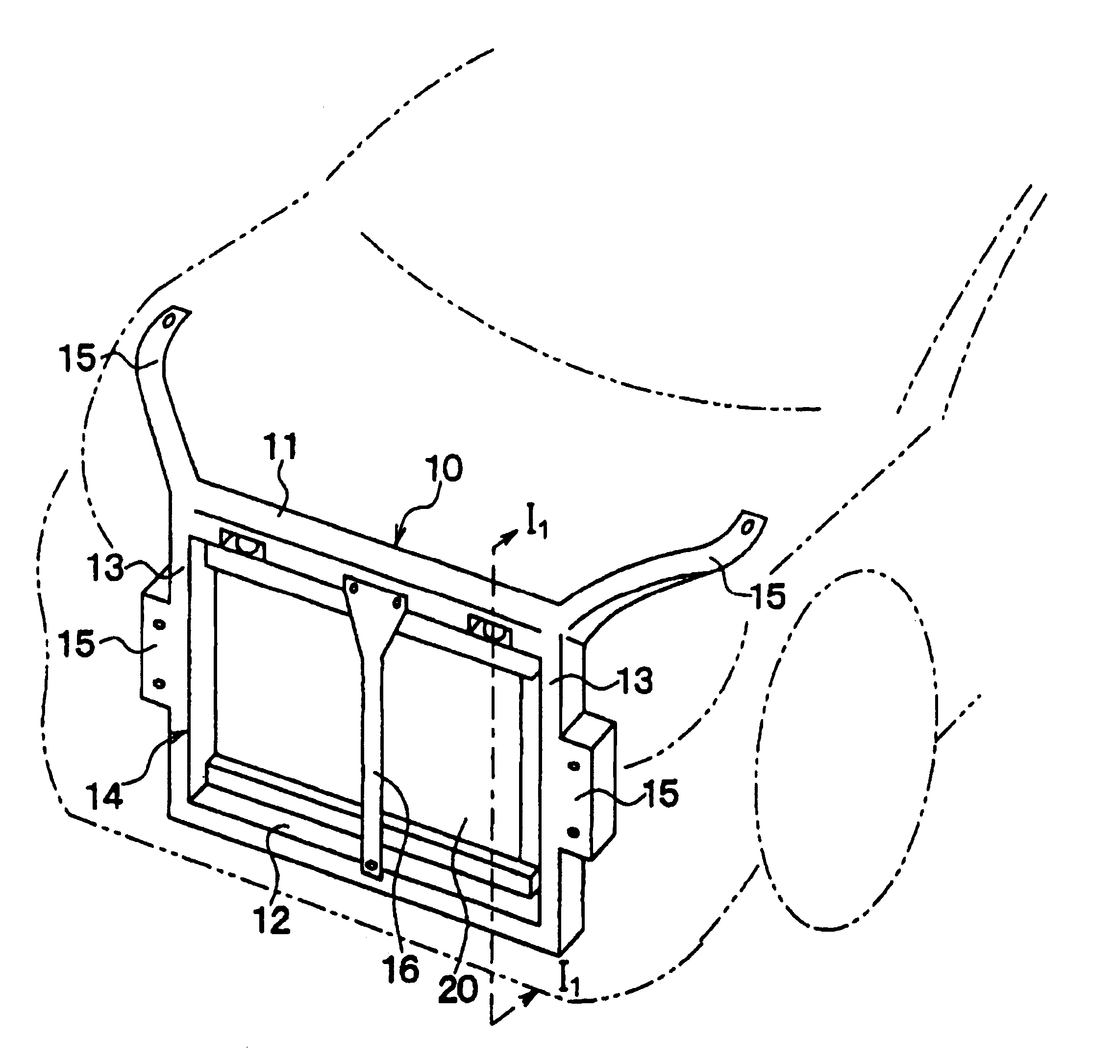
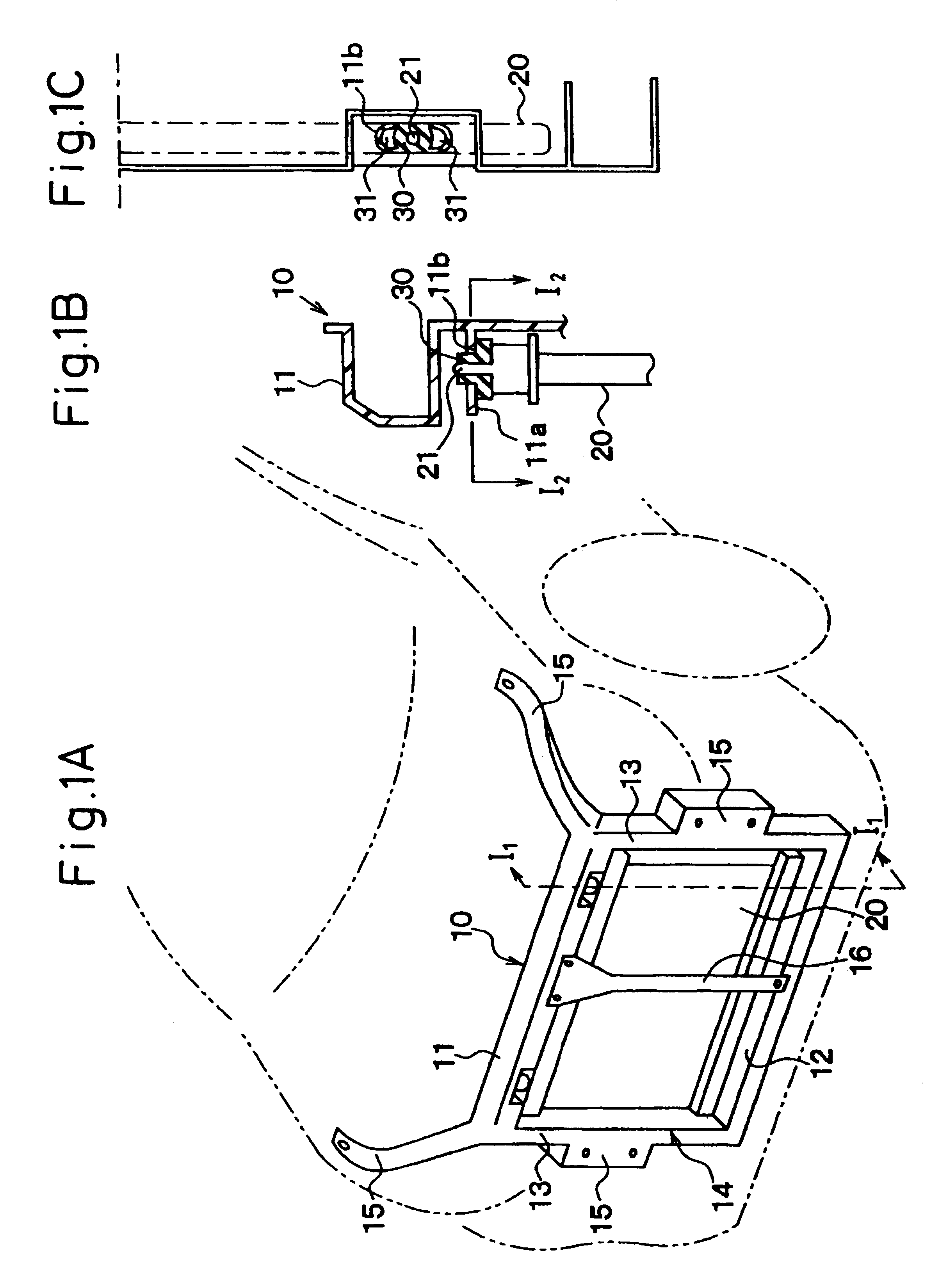
[0072]FIG. 1A is a perspective view showing a front-end structure of a vehicle according to a first embodiment of the present invention, FIG. 1B is a sectional view taken along the line I1-I1 in FIG. 1A, and FIG. 1C a sectional view taken along the line I2-I2 in FIG. 1B.

[0073]A radiator support 10 is constructed to have a rectangular frame unit 14 including a beam-like upper member 11 extending in a transverse direction of a vehicle, a beam-like lower member 12 extending in the transverse direction of the vehicle below the upper member 11 and side members 13 extending vertically to connect longitudinal end portions of the upper member 11 with longitudinal end portions of the lower member 12 and fixing portions 15 for fixing the rectangular frame unit 14 to a vehicle body.

[0074]Note that in this embodiment, the radiator support 10 is formed from resin reinforced by carbon fibers or glass fibers as a one-piece unit.

[0075]In addition, a center brace 16 is a hood lock support which exte...

second embodiment

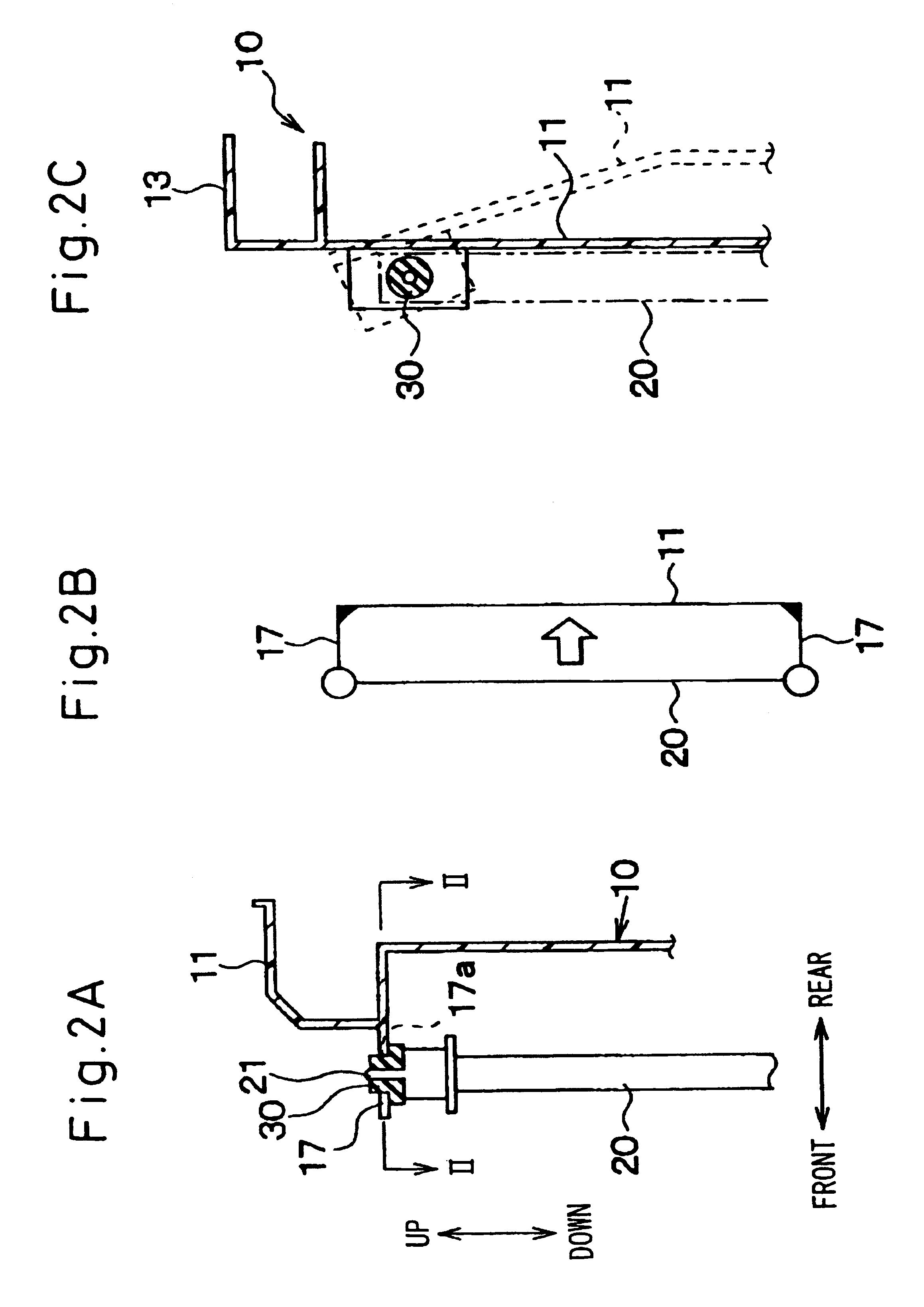
[0090]This embodiment is constructed such that a bracket 17 for holding an upper end side of a radiator 20 at a position which deviates, as shown in FIG. 2A, toward the front of the vehicle relative to an upper member 11 is provided at two left and right locations on a radiator support 10 and that external shapes of an attachment hole 17a in which a mount cushion 30 is inserted for installation and the mount cushion 30 are made circular as viewed from the top, as shown in FIG. 2C.

[0091]This embodiment is a separate embodiment from the embodiment shown in FIGS. 1A to 1C, but the embodiment provides a method for facilitating the rearward flexure of the upper member 11, an object thereof being the same as that of the first embodiment.

[0092]While the embodiment shown in FIGS. 1A to C is the example in which the longitudinal movement is allowed for by the elliptic bush, the second embodiment is an example in which a radiator support portion 21 is disposed at each end of the upper member ...

third embodiment

[0098]This embodiment is constructed such that an upper side of a radiator 20 is held, as shown in FIGS. 3A, 3B, by brackets 18 provided on side members 13 and that an opening shape of an attachment hole 18aformed in the bracket portion 18 in which a mount cushion 30 is inserted for installation and an external shape of the mount cushion 30 are made, as shown in FIG. 3B, circular as viewed from the top.

[0099]Next, the function and advantage of the embodiment will be described.

[0100]In this embodiment, since the upper side of the radiator 20 is held not at the upper member 11 but at the side members 13, the upper member 11 and the radiator 20 do not deform together, and the bending rigidity to an impact force is substantially made up of the bending rigidity of the upper member 11 alone.

[0101]Consequently, since the bending rigidity to an impact force becomes small when compared with the conventional structure, the upper member 11 is allowed to be deformed easily at the time of collis...


PUM


Abstract

An attachment portion between an upper member (11) and a radiator (20) is constructed so as to be displaced in a longitudinal direction of the upper member (11) when an impact force is applied to the upper member (11) by constructing a mount cushion (30) so as to be deformed easily in a longer diameter direction thereof. By this structure, when an impact force is applied to the upper member (11) from a front side of a vehicle, as it is not that the radiator (20) and the upper member (11) are deformed together but that the upper member (11) is deformed prior to the radiator (20), a bending rigidity to an impact force becomes smaller than a conventional case. Consequently, since the upper member is allowed to be deformed easily at the time of collision without largely reducing the mechanical strength of the upper member (11), compatibility between the requirements of protection of pedestrians and sufficient strength of the upper member (11) can be ensured.

Description

FIELD OF THE INVENTION[0001]The present invention relates to a front-end structure of a vehicle.DESCRIPTION OF THE RELATED ART[0002]Normally, a radiator is fixed to a vehicle body via a radiator support. Here, the radiator support is a so-called carrier or front end panel which is constructed to include a rectangular frame unit made up of a beam-like upper member extending in a transverse direction of the vehicle, a beam-like lower member extending in the transverse direction of the vehicle below the upper member and side members extending vertically so as to connect longitudinal ends of the upper member with longitudinal ends of the lower members, and fixing portions for fixing the rectangular frame unit to the vehicle body.[0003]Incidentally, in recent years, a front-end structure has been in demand which can reduce the injury to a pedestrian in the event he or she is hit by a vehicle.[0004]To meet this demand, the mechanical strength of the upper member which is most likely to in...

Claims


Application Information

Patent Timeline
Patent Type & Authority Patents(United States)
IPC IPC(8): B60K11/04B60R19/52B60R21/02B62D25/08
CPCB62D25/08B62D25/084B60R2019/527
Inventor OKAI, HARUMISUGIYAMA, TOSHIKIOZAWA, IKUO
Owner DENSO CORP
Why Eureka
Try Eureka