Manufacturing plant for parts, particularly vehicle body parts

a manufacturing plant and vehicle body technology, applied in the direction of turning apparatuses, gas flame welding apparatuses, soldering auxiliary devices, etc., can solve the problem of not optimal utilization of robots, and achieve the effect of improving the manufacturing plan

Inactive Publication Date: 2008-02-19
KUKA SYSTEMS
View PDF16 Cites 30 Cited by
  • Summary
  • Abstract
  • Description
  • Claims
  • Application Information

AI Technical Summary

Benefits of technology

[0006]The arrangement of one or more handling robots on additional travel axes expands the working range and improves the operation as well as the ability to reach work stations, which are arranged as multiple work stations within one processing station. This is advantageous above all for a flexible manufacturing plant, in which different types of parts are processed in a preferably free mix, the work stations being related to the particular type. Despite the enlargement of the working range of the robot and the increase in the number of work stations, the number of handling robots needed can be kept low.
[0007]It is particularly advantageous if handling and processing robots are arranged next to one another on a common travel axis. As a result, processing and handling operations, especially transport operations, can take place simultaneously, and, moreover, a plurality of parts can be processed and / or handled simultaneously. Due to the common travel axis, the total number of robots needed can in turn be kept low. One or more robots may also have a dual function as a handling robot and as a processing robot.
[0008]The processing stations may be arranged separated from one another, in which case transfer points with intermediate storage units, buffer storage units or the like are formed in the transfer line. The transfer line may, moreover, branch out, which makes possible the better utilization of the individual processing stations. As a result, the preset cycle time and the flow of material can, in addition, be made flexible.

Problems solved by technology

Relatively many robots are needed in such cells, and, moreover, these robots are not utilized optimally.

Method used


Image

  • Manufacturing plant for parts, particularly vehicle body parts
  • Manufacturing plant for parts, particularly vehicle body parts
  • Manufacturing plant for parts, particularly vehicle body parts

Examples


Embodiment Construction

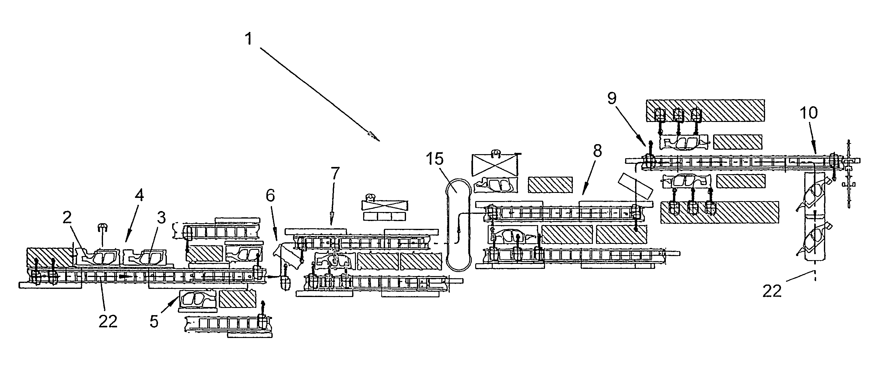
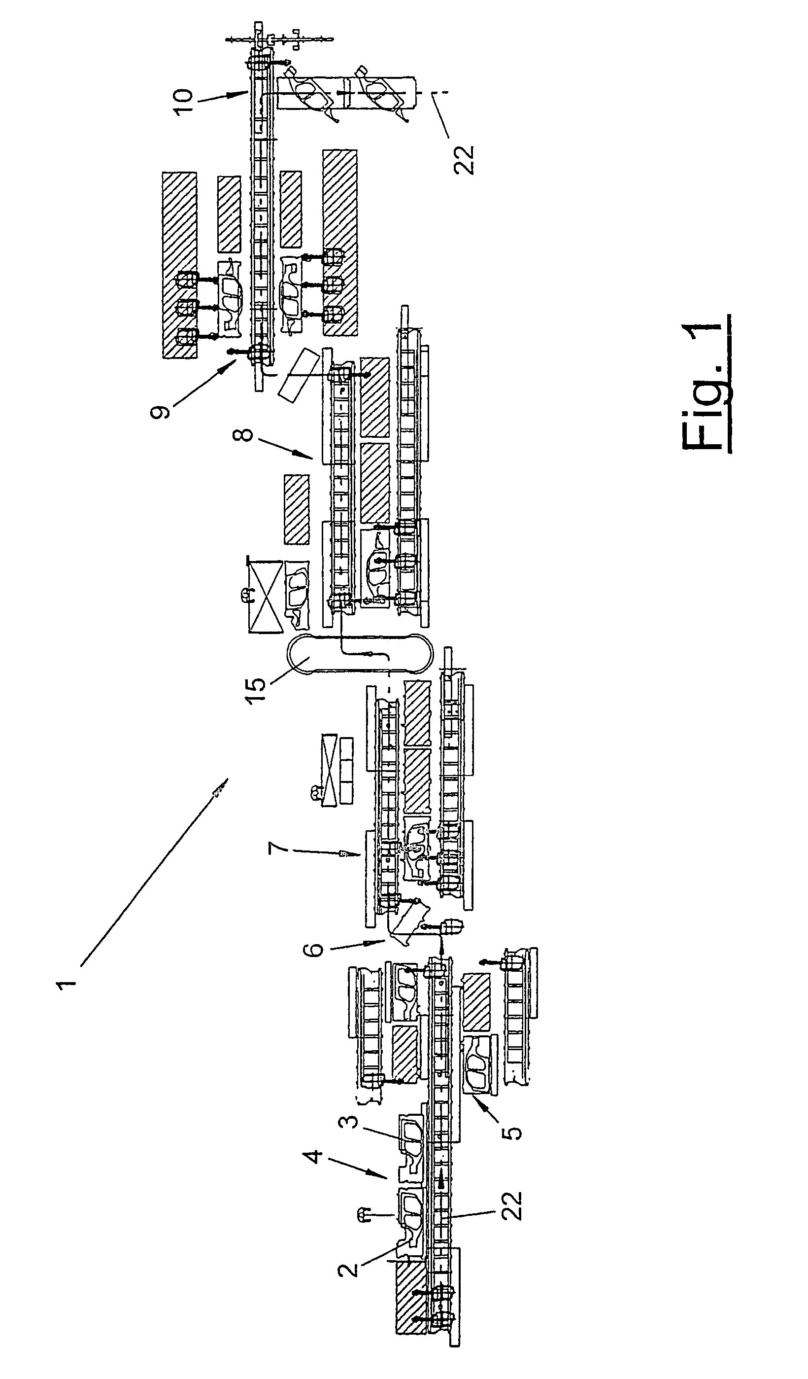
[0016]Referring to the drawings in particular, FIG. 1 schematically shows a top view of a manufacturing plant (1) for components (2, 3), which are preferably body parts of vehicle bodies, especially body shells. These may be, e.g., the shown side panels of a vehicle body. A plurality of different types of parts (2, 3) of the same kind can be preferably processed in the manufacturing plant (1) next to one another and preferably in a free mix. Two different types of parts (2, 3) are shown in the embodiment shown. Measures are taken here to also make it possible to process three or more or any other desired number of types of parts.

[0017]The manufacturing plant (1) comprises a plurality of processing stations (4 through 10), which are arranged one after another along a transfer line (22). The parts (2, 3) are processed in the individual stations (4 through 10) and then passed on from station to station. The transfer line (22) may have any desired shape and extension. It may have a line...


PUM

PropertyMeasurementUnit
flexibleaaaaaaaaaa
shapeaaaaaaaaaa
right anglesaaaaaaaaaa

Abstract

A manufacturing plant (1) is provided for vehicle body parts (2, 3). The manufacturing plant includes a number of processing stations (4, 5, 6, 7, 8, 9, 10), which are situated one behind the other along a transfer line (22), and of a number of multiaxial robots (18, 19). In at least one processing station (4, 5, 6, 7, 8, 9, 10), one or more handling robots (18) for transporting parts is / are arranged on at least one axis of travel (20, 21). Next to the handling robot (18), one or more processing robots (19) is / are displaceably arranged on the same axis of travel (20). Working locations (11, 12) are arranged on both sides of a common axis of travel (20), whereby another common axis of travel can be provided on the rear side of the working locations.

Description

CROSS REFERENCE TO RELATED APPLICATIONS[0001]This application is a United States National Phase application of International Application PCT / EP2003 / 014766 and claims the benefit of priority under 35 U.S.C. §119 of German Application DE 203 04 022.8 filed Mar. 12, 2003, the entire contents of which are incorporated herein by reference.FIELD OF THE INVENTION[0002]The present invention pertains to a manufacturing plant for components, especially body parts.BACKGROUND OF THE INVENTION[0003]Such a manufacturing plant is known from DE 298 04 850 U1.It comprises a plurality of processing stations or cells, which are arranged in a row along a transfer line. A central transport robot, which is designed as a stationarily positioned multiaxial articulated arm robot and transports the parts, is present within each cell. Within the cell, there are a plurality of work stations, at which the parts are processed, especially joined, by processing robots. The parts are transferred between the cells v...

Claims


Application Information

Patent Timeline
Patent Type & Authority Patents(United States)
IPC IPC(8): B23P21/00B23K37/047B62D65/00B62D65/02
CPCB23K37/047B23P21/004B62D65/02B23K2201/006Y10T29/534Y10T29/5196Y10T29/49829B23P2700/50B23K2101/006
Inventor DEGAIN, MICHAELLONG, ROBERTMOSER, HANS
Owner KUKA SYSTEMS
Why Eureka
Try Eureka