
Tubular threaded joint with trapezoid threads having convex bulged thread surface

a tubular threaded joint and convex technology, applied in the direction of screw threaded joints, hose connections, rod connections, etc., can solve the problems of high cost and high degree of precision of threading machined, and achieve the effect of improving the behaviour of breakout/overtorquing, increasing the resistance to breakout or overtorquing, and increasing the frictional surfa

Inactive Publication Date: 2008-02-19
VALLOUREC OIL & GAS FRANCE SAS +1
View PDF10 Cites 17 Cited by
  • Summary
  • Abstract
  • Description
  • Claims
  • Application Information

AI Technical Summary

Benefits of technology

The invention is about creating threaded tubular connections with trapezoidal threads that require higher torque to break out or beyond their made up position. This helps prevent galling and other damage to the threaded connections. The invention also aims to provide threaded tubular connections with wedge threads or threads with axial interference that can be machined with normal dimensional tolerances. The invention uses a male threaded element with trapezoidal threads and a female threaded element with internal female threads that mates with the male threaded element. The male and female threaded elements are made up with a given make-up torque and the invention provides a threaded tubular connection with trapezoidal threads that requires higher torque to break out or beyond its made up position. This helps prevent galling and other damage to the threaded connections. The invention also uses a convexly rounded face on the threaded elements to create a point contact with the corresponding face in contact, which increases resistance to breakout or overtorquing. The invention aims to provide threaded tubular connections with wedge threads or threads with axial interference that can be machined with normal dimensional tolerances.

Problems solved by technology

This means that the threadings must be machined with a high degree of precision, and thus at a high cost.

Method used


Image

  • Tubular threaded joint with trapezoid threads having convex bulged thread surface
  • Tubular threaded joint with trapezoid threads having convex bulged thread surface
  • Tubular threaded joint with trapezoid threads having convex bulged thread surface

Examples


Embodiment Construction

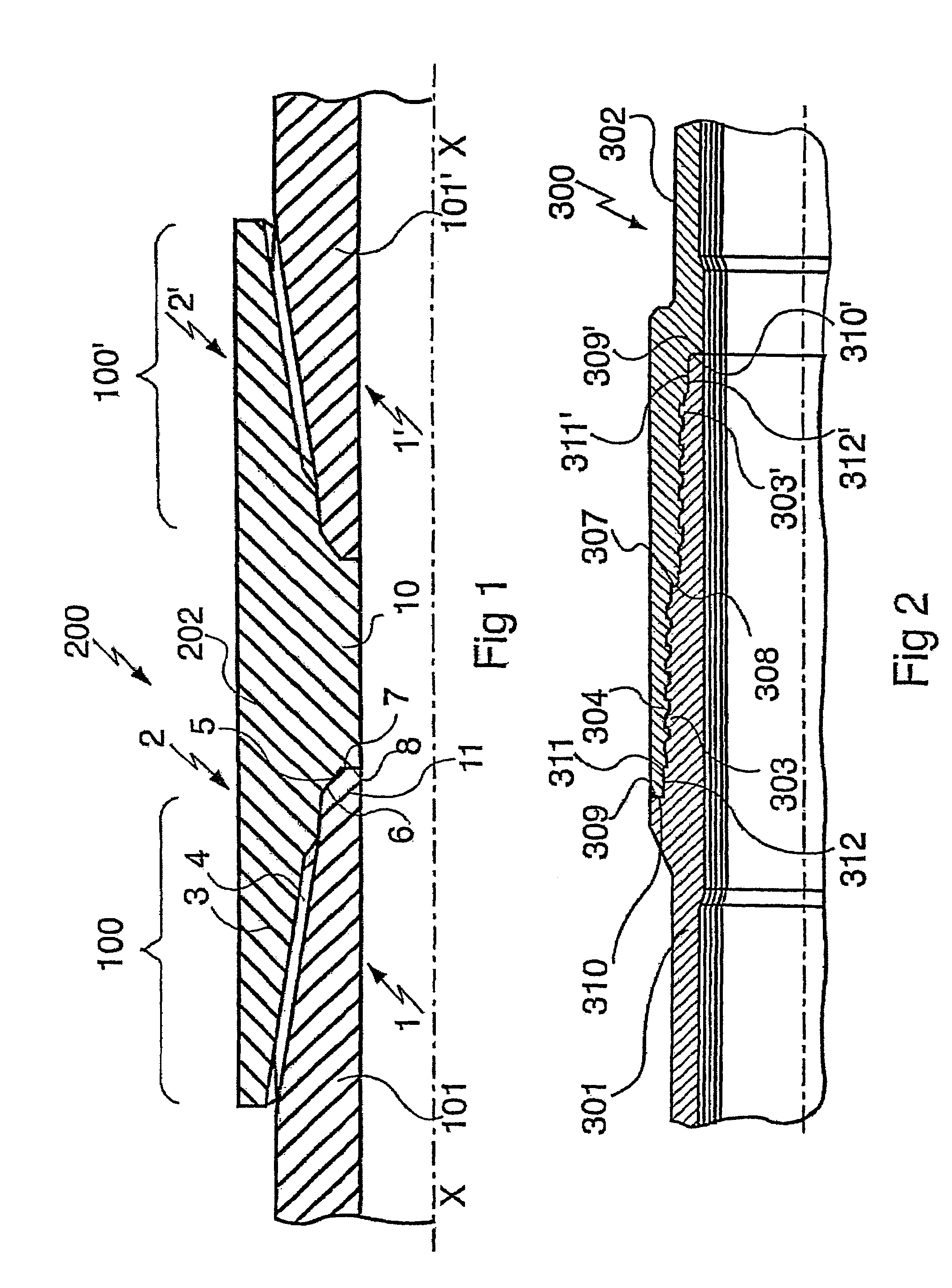
[0075]FIG. 1 shows a threaded and coupled connection 200 between two great length pipes 101, 101′.

[0076]The term “great length pipe” means pipes several metres long, for example about 10 m long.

[0077]Such pipes are usually connected to constitute casing strings or tubing strings for hydrocarbon wells or drillpipe strings for the same wells.

[0078]The pipes can be formed from any non alloyed, light alloyed or heavy alloyed steel, or even ferrous or non ferrous alloys to adapt them to the different working conditions: amount of mechanical stress, corrosive nature of fluid inside or outside the pipes.

[0079]It is also possible to use steel pipes that have low corrosion resistance provided with a coating, for example of a synthetic material that prevents any contact between the steel and the corrosive fluid.

[0080]The ends of pipes 101, 101′ are provided with identical male threaded elements 1, 1′ and are connected via a coupling 202 each end of which is provided with a female threaded ele...


PUM


Abstract

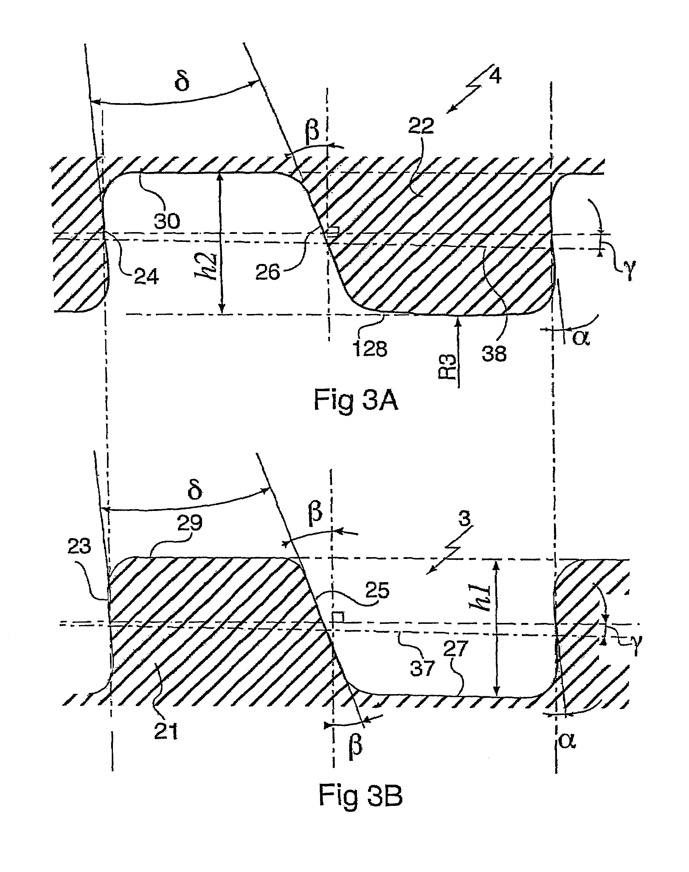
A threaded tubular connection includes two elements, male and female, made up one into the other to a given torque in which, prior to making up, at least one thread face under contact pressure has a convexly rounded shape that is continuous over its width with a radius of curvature in the range 2 to 60 mm and is in point contact with the corresponding face of the mating element. Such a threaded connection has an increased resistance to breakout or to overtorquing. In one embodiment, the convexly rounded face is a male or female thread flank and one of the male or female threads includes a groove opening into the thread crest to render flexible either the convexly rounded flank or the corresponding flank. Such a geometry can accommodate variations in contact between the flanks.

Description

BACKGROUND OF THE INVENTION[0001]1. Field of the Invention[0002]The invention relates to threaded tubular connections.[0003]2. Discussion of the Related Art[0004]Threaded tubular connections can include a male threaded element and a female threaded element with trapezoidal threads located at the end of pipes to be connected; the threaded elements can be disposed as well as the end of great length pipes as at the end of short length pipes such as couplings.[0005]Such threaded tubular connections are in particular used to constitute casing strings or tubing strings or drillpipe strings for hydrocarbon wells or for similar wells such as geothermal wells.[0006]They have, for example, been defined in American Petroleum Institute (API) specifications API 5B and 5CT as tapered threadings with trapezoidal threads termed “buttress” threads.[0007]The trapezoidal threads comprise a stabbing flank on the side of the threads directed towards the free end of the threaded element under considerati...

Claims


Application Information

Patent Timeline
Patent Type & Authority Patents(United States)
IPC IPC(8): F16L25/00F16L15/02F16B7/18F16L15/00F16L15/06
CPCF16L15/001F16L15/002E21B17/042F16L15/06
Inventor NOEL, THIERRYROUSSIE, GABRIELVARENNE, EMMANUEL
Owner VALLOUREC OIL & GAS FRANCE SAS
Learn More