
Luminescence assays

a technology of luminescence and assays, applied in the field of luminescence assays, can solve the problems of sensitivity limit set by background, inability to efficiently transfer energy, and relatively insensitive energy transfer processes

Inactive Publication Date: 2008-02-19
PHOTONIC RES SYST
View PDF8 Cites 9 Cited by
  • Summary
  • Abstract
  • Description
  • Claims
  • Application Information

AI Technical Summary

Benefits of technology

[0015]It is therefore an object of the present invention

Problems solved by technology

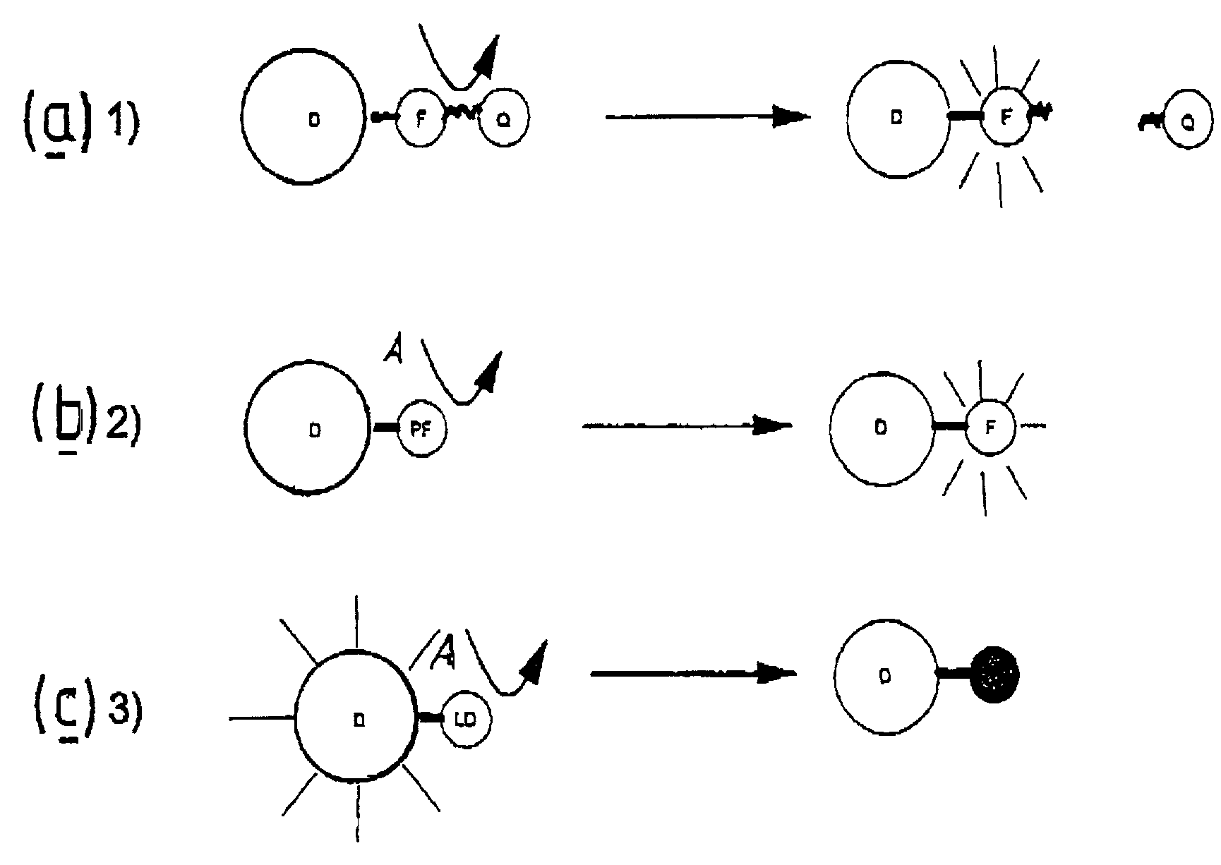
As the linkage is broken the donor and acceptor become separated and efficient transfer of energy is no longer possible.
Most assays involving energy transfer processes are relatively insensitive and can have limited dynamic range.
One problem with all luminescence detection is the sensitivity limit set by background.
Unfortunately, luminescence energy transfer is commonly troubled by background from a variety of causes.
Ideal conditions are rarely achieved however and the following potential difficulties and sources of background must be considered:It is often difficult to avoid some level of direct excitation of the acceptor species by radiation used to excite the donor.
In assays where the acceptor is luminescent, this means that there is usually a background of luminescence from the acceptor, even in the absence of any energy transfer from the donor and this in turn limits dynamic range of any assay using the donor-acceptor pair.Exciting radiation is capable of exciting luminescence from impurities or other unwanted components of the sample.The donor might emit some radiation at a wavelength which overlaps with the passband of the optical filters used to isolate emission from the acceptor, so that a signal is detected in absence of energy transfer.
These and related problems limit the scope, sensitivity and dynamic range of assays based on energy transfer processes.

Method used


Image

  • Luminescence assays
  • Luminescence assays
  • Luminescence assays

Examples


Embodiment Construction

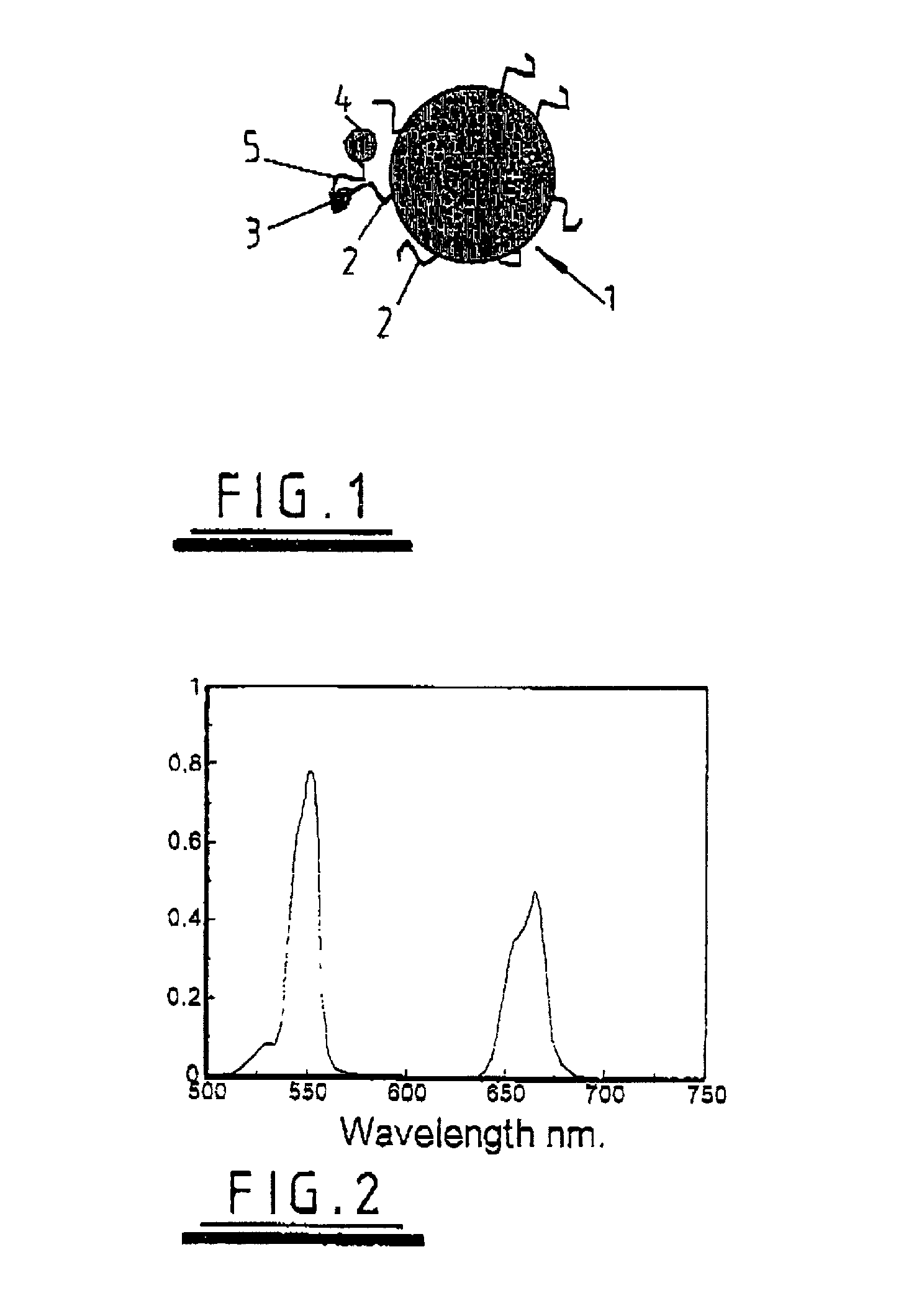
[0021]According to the present invention there is provided a method of performing an energy transfer luminescence assay to determine an analyte in which a donor species is irradiated to raise the donor species to an excited state, and the analyte causes a change in the excitation condition of at least one of the donor species and an acceptor species and said change is monitored to determine the analyte wherein[0022](i) the donor species is provided as, in or adsorbed to a solid phase and is an up-conversion medium capable of effecting, by energy pooling or otherwise, an energy transition to an excited state by absorption of electromagnetic radiation having an energy less than that of said transition,[0023](ii) the acceptor species is bound or is capable of being bound directly or indirectly to the surface of said solid phase,[0024](iii) the donor species is irradiated with said electromagnetic radiation, and[0025](iv) luminescence is detected in at least one spectral region characte...


PUM

PropertyMeasurementUnit
Decay rateaaaaaaaaaa
Efficiencyaaaaaaaaaa
Absorbanceaaaaaaaaaa

Abstract

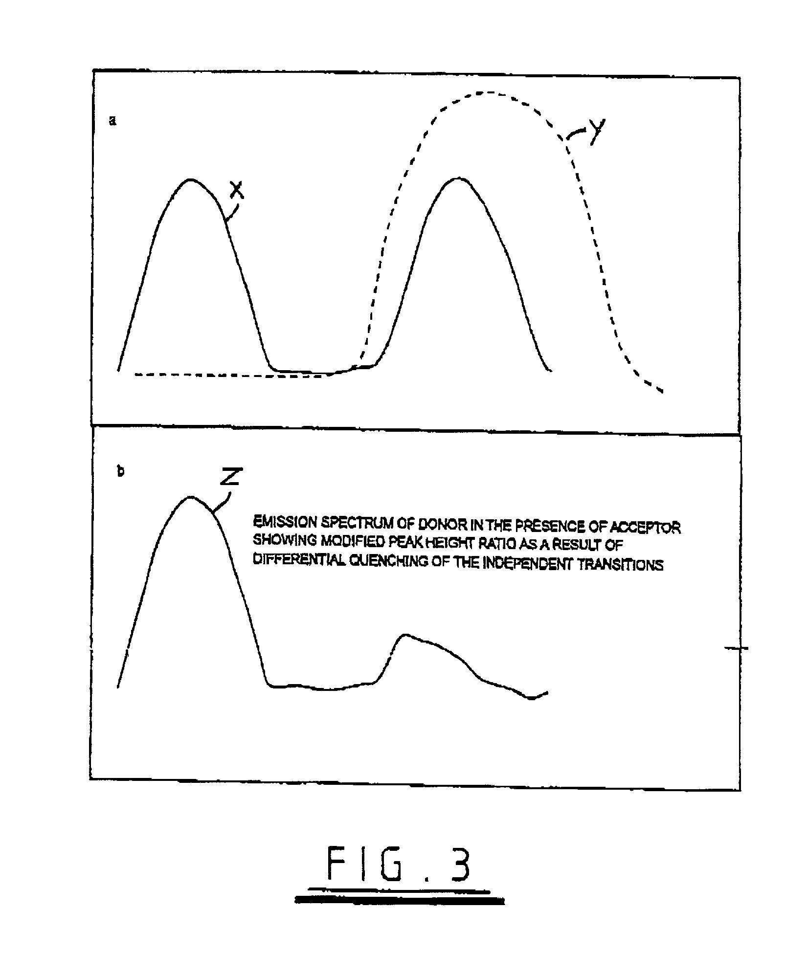
A method of detecting an analyte is described in which an up-converting luminescent species that is excited by absorption of long wavelength light is provided as a donor of energy to an acceptor species that can be bound to, or generated in proximity to, the luminescent species. The analyte either alters the proximity between the luminescent species and the acceptor species or alters the absorbance or luminescence properties of the acceptor species. The luminescent energy donor is excited with long wavelength light and transfers up-converted energy to the proximate acceptor species and this transfer of energy is detected by measurement of appropriate luminescence properties of either the donor or of the acceptor or both.

Description

CROSS-REFERENCE TO RELATED APPLICATIONS[0001]This application is a continuation-in-part of application Ser. No. 09 / 381,838, filed on Dec. 1, 1999, now abandoned.BACKGROUND OF THE INVENTION[0002]The present invention relates to luminescence assays based on transfer of excitation energy from a donor species to an acceptor species.[0003]The present invention relates to luminescence assays based on transfer of excitation energy from a donor species to an acceptor species.[0004]Fluorescence, phosphorescence and related technologies (herein referred to as “luminescence” to include in this context all processes where energy is emitted subsequent to an excitation process triggered by absorption of electromagnetic radiation) are now widely used in a variety of analytical schemes. Luminescent materials are used as tracers on the basis of the high detection sensitivity that can be achieved, but are also used as environmentally responsive “probes” to monitor local conditions, such as pH, ion co...

Claims


Application Information

Patent Timeline
IPC IPC(8): G01N21/76C12Q1/68G01N21/64G01N33/543
CPCC12Q1/6818G01N21/6428G01N33/54373C12Q1/6837Y10T436/13G01N2021/6432Y10S435/968C12Q2565/101C12Q2563/155C12Q2565/519C12Q2563/103
Inventor MORGAN, CHRISTOPHER G.
Owner PHOTONIC RES SYST
Learn More