Cold shield for cryogenic camera

a cryogenic camera and shielding technology, applied in the field of cold shields, can solve the problems of misalignment between the lens and the focal plane array, the application of multi-image detector assemblies in cryogenic applications, and the inability to provide feedback

Active Publication Date: 2008-02-19
NORTHROP GRUMMAN SYST CORP
View PDF10 Cites 10 Cited by
  • Summary
  • Abstract
  • Description
  • Claims
  • Application Information

AI Technical Summary

Benefits of technology

[0008]The present invention provides a cold shield applied to a cryogenic camera. The cold shield reflects external thermal radiation away from the cryogenic camera, so as to shield the cryogenic camera in a cryogenic temperature such that no internal thermal radiation will be generated. The cryogenic camera comprises a lens assembly and a focal plane array. The cold shield comprises an upper cold shield member for holding the lens assembly and a lower cold shield member for holding the focal plane array. The upper cold shield member fits over the lower cold shield member by contact friction, such that limited translation and rotation of the lower cold shield member relative to the upper cold shield member are allowable. Therefore, the cold shield allows a fine adjustment for aligning the lens assembly to the focal plane array.
[0009]The upper cold shield member comprises a lens holder for holding the lens assembly and a holder mount for mounting the lens holder. The holder mount includes at least one bump protruding from an interior sidewall thereof. The bump provides the contact friction to the lower cold shield member fitted within the lens holder. The upper cold shield member further comprises a cap for securing the lens assembly held by the lens holder. Before the cold shield and the cryogenic camera shielded thereby are cooled down to a cryogenic temperature, an adhesive, preferably cryogenically stable adhesive, is applied between the upper and lower cold shield members, such that the relative position of the lens assembly and the focal plane array is fixed. Each of the upper cold shield member and the lower cold shield member includes a window to prevent blocking propagation of an imaging light.
[0011]The lower hollow cylinder has an outer diameter smaller than an inner diameter of the upper hollow cylinder. Preferably, the difference between the outer diameter and the inner diameter is about 0.005 inches. Therefore, the lower hollow cylinder can be inserted into the upper hollow cylinder with a gap therebetween. The upper hollow cylinder further comprises a plurality of bumps protruding inwardly from an interior sidewall to provide frictions contact to the lower hollow cylinder inserted therein. In this manner, the lower cold shield member can be translated and rotated within the upper cold shield member. Consequently, the lens assembly held by the upper cold shield member can be translated and rotated relative to the focal plane array retained in the lower cold shield member. Therefore, a fine focus adjustment and alignment between the lens assembly and the focal plane array can be performed.

Problems solved by technology

However, since the focus and alignment of the camera are sensitive to temperature, there is a demand for applying a cryogenic system to the camera to suppress the noise caused by thermal radiation.
However, the cryogenic application of such multi-image detector assembly was not addressed in this patent.
Such calculations are done coarsely without any feedback.
However, as the positioning stage is not accessible from outside of the dewar, when a new position of the lens is required, the lens and the focal plane array have to be warmed up to room temperature for adjustment of the lens position relative to the focal plane.
Further, as the lens is supported by the positioning stage in a floating manner relative to the focal plane array, misalignment between the lens and the focal plane array occurs every time when the system is warmed up.
It is thus very laborious for obtaining the optimal lens positions relative to the focal plane.

Method used


Image

  • Cold shield for cryogenic camera
  • Cold shield for cryogenic camera
  • Cold shield for cryogenic camera

Examples


Embodiment Construction

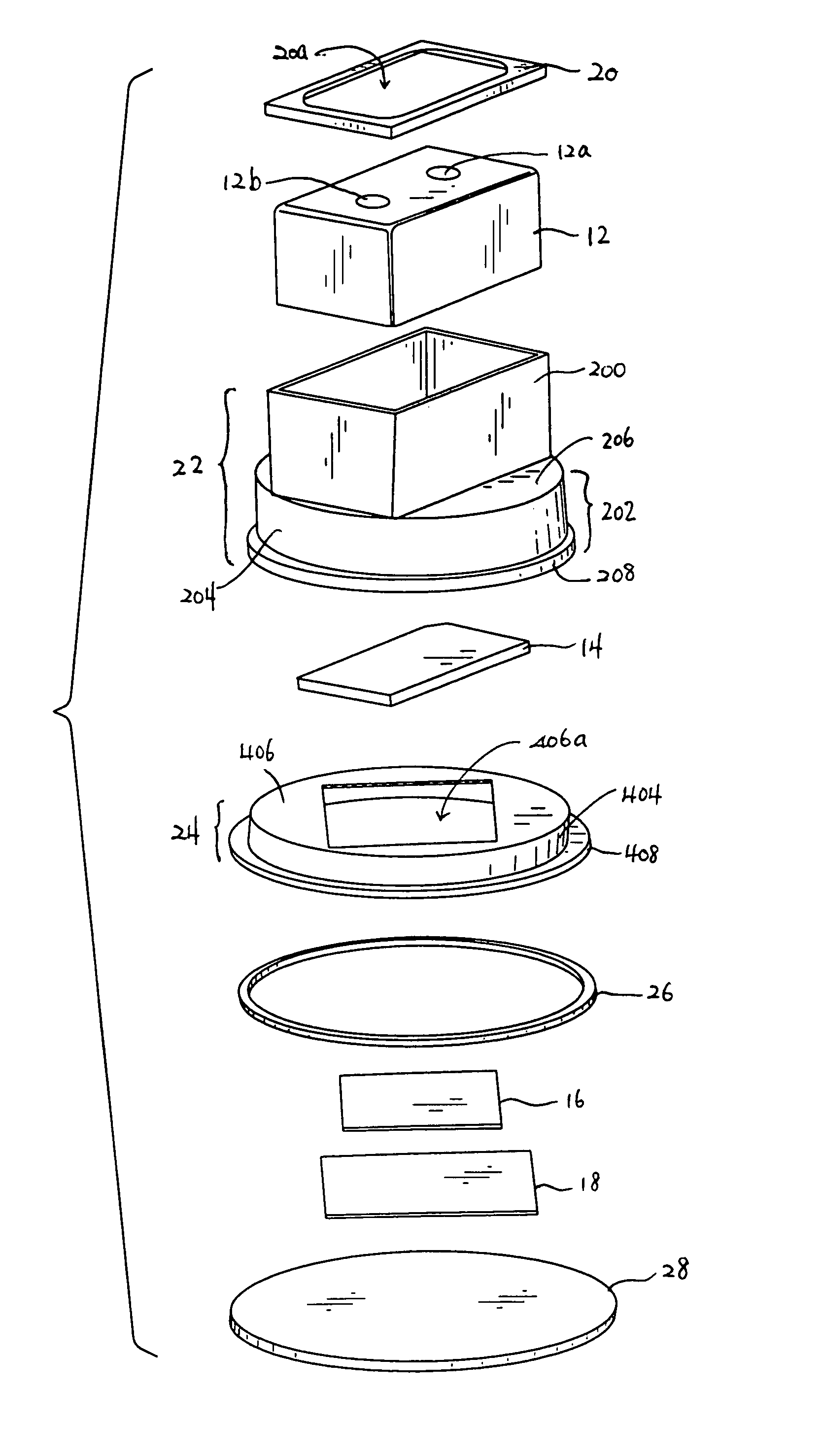
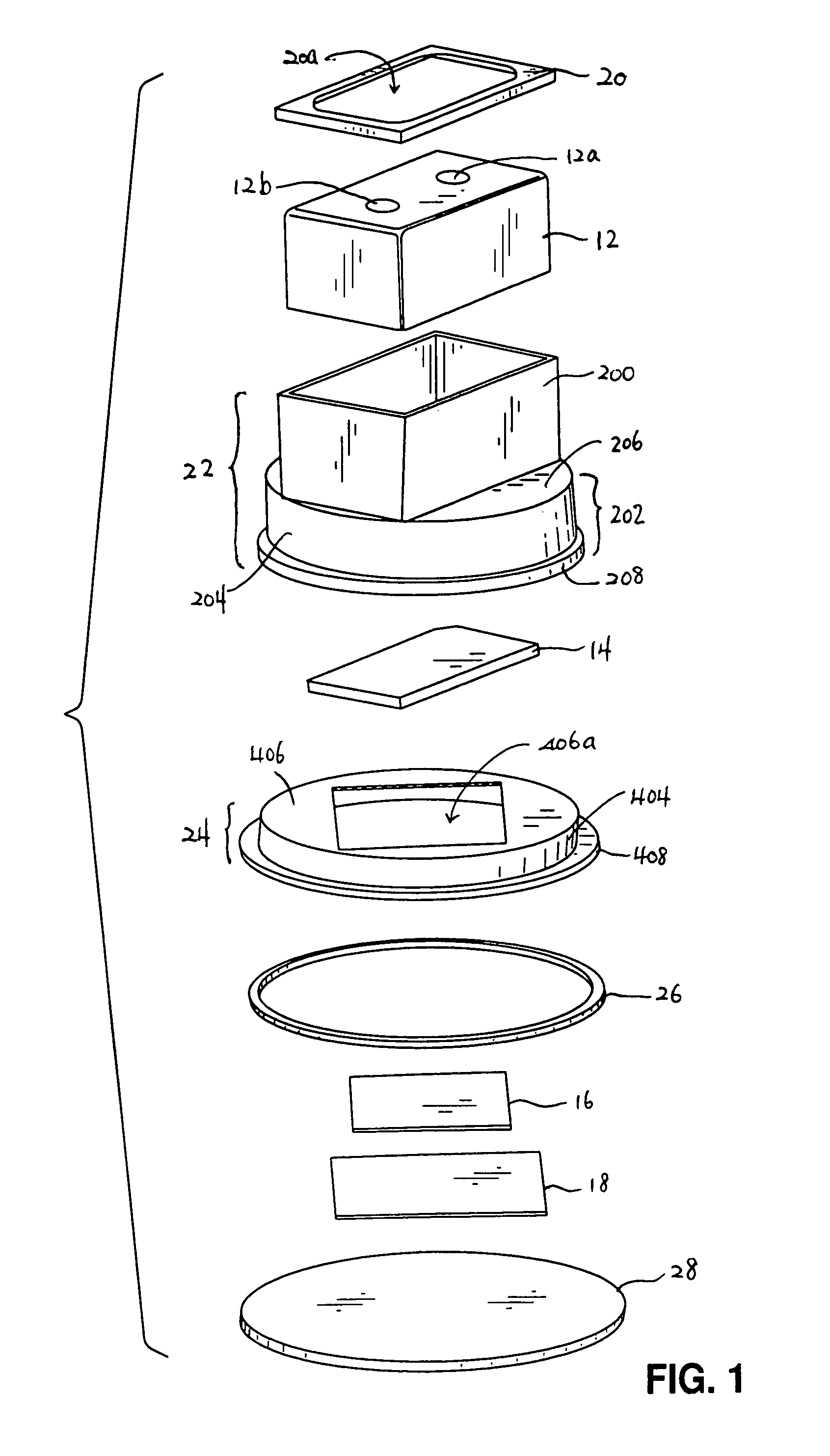
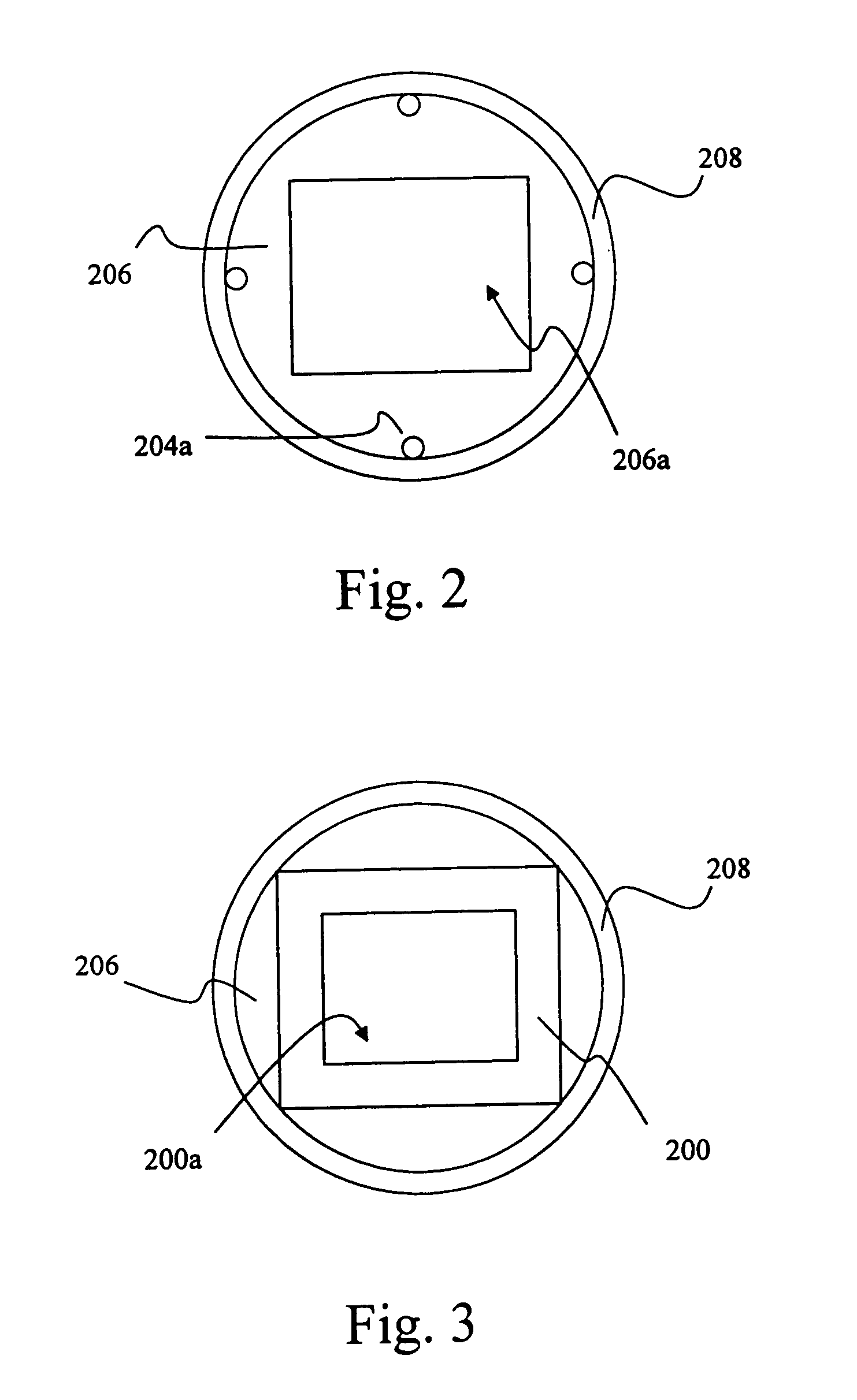
[0016]As shown in FIG. 1, a cryogenic camera, including a multiple-element lens assembly 12, a filter 14, a focal plane array 16 and a readout integrated circuit 18, is shielded by a cold shield. In this embodiment, a standard cryogenically cooled infrared (IR) optical system is used. It is appreciated that the application of the cold shield can be expanded to any optical system for image registration without exceeding the spirit and scope of the present invention. Both the cryogenic camera and the cold shield shielding are disposed in a cryo-vacuum dewar and cooled to cryogenic temperatures. In such way, external radiation can be reflected by the cold shield, while the elements of the camera, including the multiple-element lens assembly 12, the filter 14, the focal plane array 16 and the readout integrated circuit 18, are cooled down to a temperature so low that no radiation is emitted to cause thermal noise. In practical application, the multiple-element lens assembly 12 is dispos...


PUM


Abstract

A cold shield of a cryogenic camera. The cold shield reflects external thermal radiation away from the cryogenic camera, so as to shield the cryogenic camera in a cryogenic temperature such that no internal thermal radiation will be generated. The cryogenic camera has a lens assembly and a focal plane array. The cold shield has an upper cold shield member for holding the lens assembly and a lower cold shield member for holding the focal plane array. The upper cold shield member fits over the lower cold shield member by contact friction, such that limited translation and rotation of the lower cold shield member relative to the upper cold shield member are allowable. Therefore, the cold shield allows a fine adjustment for aligning the lens assembly to the focal plane array.

Description

CROSS-REFERENCE TO RELATED APPLICATIONS[0001]Not ApplicableSTATEMENT RE: FEDERALLY SPONSORED RESEARCH / DEVELOPMENT[0002]Not ApplicableBACKGROUND OF THE INVENTION[0003]The present invention relates in general to a cold shield, and more particularly, to a cold shield for shielding a cryogenic camera and reducing thermal noise of images registered by the cryogenic camera.[0004]Image registration is a fundamental task required in many applications of image processing which involves taking two or more images and aligning them so as to either eliminate differences between them or highlight the salient differences for the purpose of study. To obtain sub-pixel accuracy of the registration, a well registered and stable camera configuration is required. An integrated lens has been used in the single element multiple field cameras. In the integrated lens design, the lens position is constantly referenced to the same mechanical plane referred as a focal plane for minimizing allowable movements c...

Claims


Application Information

Patent Timeline
Patent Type & Authority Patents(United States)
IPC IPC(8): G01J5/02H04N5/225
CPCH04N5/2253H04N5/2254H04N23/52H04N23/55H04N23/54
Inventor MINARIK, PHILIP R.YOO, SUNG-SHIK
Owner NORTHROP GRUMMAN SYST CORP
Why Eureka
Try Eureka