
Nozzle plate of inkjet head and method for producing the same

a technology of inkjet head and nozzle plate, which is applied in the direction of printing and inking apparatus, can solve the problems of deteriorating the accuracy of ejecting ink, and achieve the effect of enhancing the uniform thickness of the water repellent film formed on the nozzle pla

Active Publication Date: 2008-02-26
BROTHER KOGYO KK
View PDF7 Cites 2 Cited by
  • Summary
  • Abstract
  • Description
  • Claims
  • Application Information

AI Technical Summary

Benefits of technology

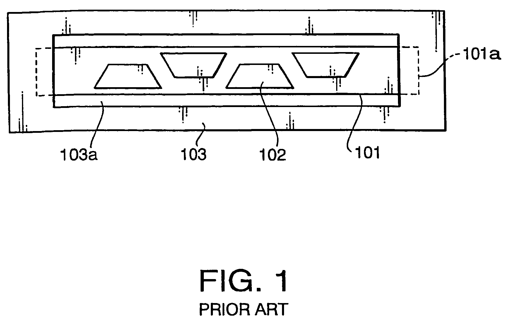
[0011]The present invention is advantageous in that it provides a nozzle plate configured such that variations in diameters of nozzles are decreased, and provides a producing method of such a nozzle plate.
[0013]Since in the above mentioned method the gap is smaller or equal to 10 mm, it becomes possible to uniform a current flowing through the nozzle plate. Consequently, uniformity of the thickness of the water repellent film formed on the nozzle plate is enhanced.
[0024]With this configuration, it becomes possible to uniform a distribution of a current flow flowing through the nozzle plate. Consequently, uniformity of the thickness of the water repellent film formed on the nozzle plate is enhanced.
[0031]With this configuration, it becomes possible to uniform a distribution of a current flow flowing through the nozzle plate. Consequently, uniformity of the thickness of the water repellent film formed on the nozzle plate is enhanced.

Problems solved by technology

If the ink residues remain around an ejecting side of the nozzle, variations in an ejecting direction of the ink and / or in an ejecting amount of the ink may occur, which deteriorates accuracy of ejecting operation of the ink.

Method used


Image

  • Nozzle plate of inkjet head and method for producing the same
  • Nozzle plate of inkjet head and method for producing the same
  • Nozzle plate of inkjet head and method for producing the same

Examples


Embodiment Construction

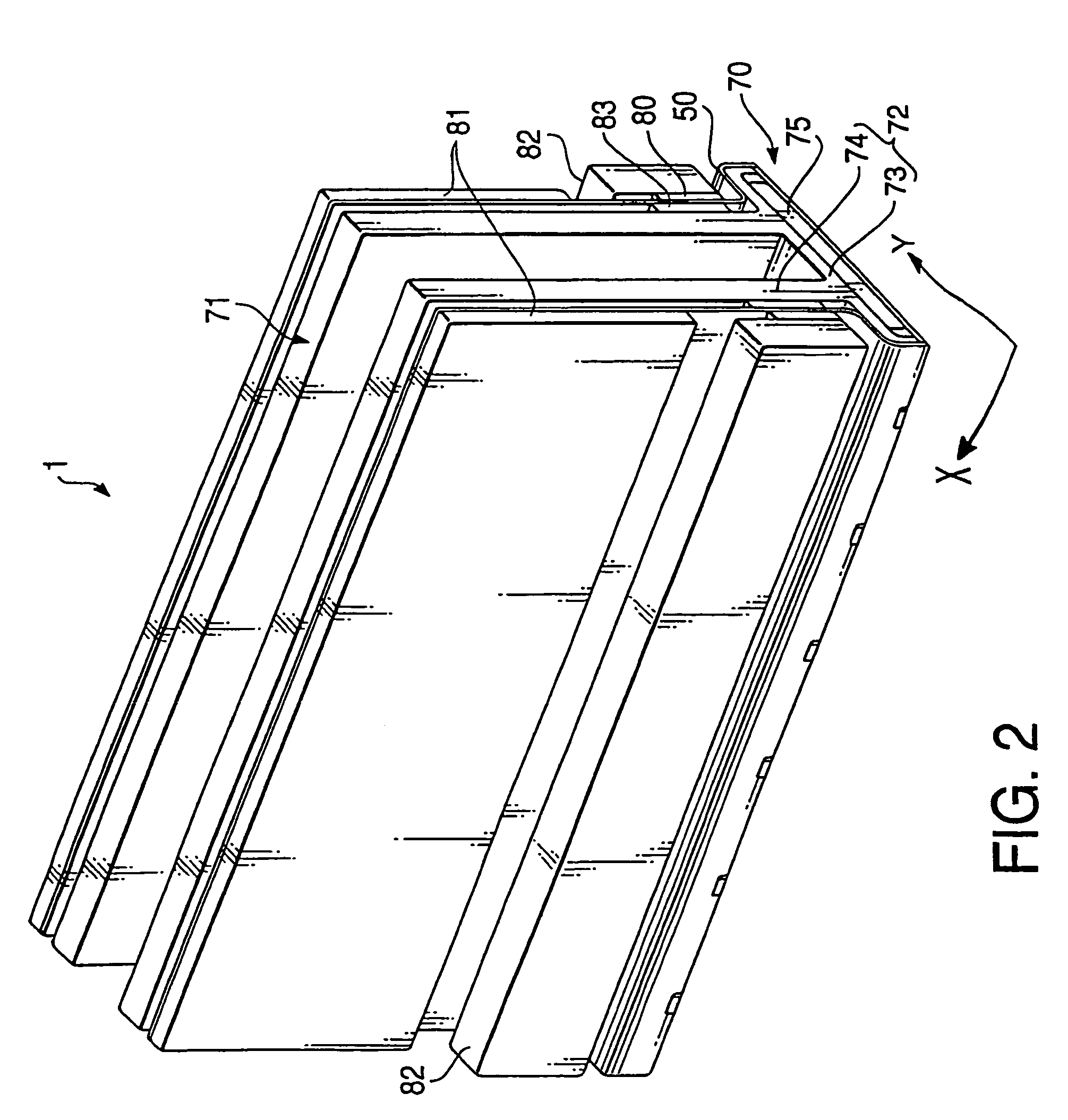
[0049]FIG. 2 is a perspective view of an inkjet head 1 according to an embodiment of the invention. As shown in FIG. 2, the inkjet head 1 has a head unit 70 facing a sheet of paper. The head unit 70 is supported by a base 71. The inkjet head 1 is used in a printing device, such as a printer, such that the inkjet head 1 is moved in a X direction (i.e., a main scanning direction) while the sheet of paper is moved in a Y direction (i.e., an auxiliary scanning direction) to form a two dimensional image on the sheet of paper.

[0050]As described in detail below, the head unit 70 includes an ink flow channel unit 2, in which ink flow channels each having a pressure chamber 10 and a nozzle 8 are formed, and an actuator unit 4 which applies pressure to ink in the pressure chamber 10 (see FIGS. 3 and 5).

[0051]As shown in FIG. 2, the base 71 has a base block 75 and a holder 72. The base block 75 is cemented to a back side of the base unit 70 to hold the base unit 70. The holder 72 has a body un...


PUM


Abstract

There is provided a method for producing a nozzle plate of an inkjet head having a plurality of nozzles for ejecting ink. The method includes: preparing a nozzle plate base which has an electrical conductivity, the nozzle plate base including a nozzle plate, an outer frame surrounding the nozzle plate, and a plurality of connecting portions which connect the nozzle plate to the outer frame; forming the plurality of nozzles through the nozzle plate; dipping the nozzle plate base into an electrolytic solution; and energizing the outer frame of the nozzle plate base to plate the nozzle plate with a water repellent film. In this method, a gap formed between the nozzle plate and the outer frame is smaller than or equal to 10 mm.

Description

BACKGROUND OF THE INVENTION[0001]The present invention relates to a nozzle plate of an inkjet head and a producing method thereof, and more particularly to water repellent finishing of the nozzle plate.[0002]In general, the inkjet head provided in printing devices such as a printer and a facsimile machine has the nozzle plate on which a plurality of nozzles for ejecting ink are arranged. In the inkjet head, the nozzles respectively communicate with pressure chambers, to which actuators such as a piezoelectric element are respectively attached.[0003]By operating the actuator, a certain amount of ink pressurized in the pressure chamber is introduced to the nozzle, and then is ejected from the nozzle.[0004]If the ink residues remain around an ejecting side of the nozzle, variations in an ejecting direction of the ink and / or in an ejecting amount of the ink may occur, which deteriorates accuracy of ejecting operation of the ink. For this reason, an ejecting side surface of the nozzle pl...

Claims


Application Information

Patent Timeline
Patent Type & Authority Patents(United States)
IPC IPC(8): B41J2/14B41J2/165B41J2/16B41J2/135
CPCB41J2/1433B41J2/1606B41J2/162B41J2/1628B41J2/1629B41J2002/14217B41J2002/14225B41J2002/14459B41J2202/20
Inventor KOBAYASHI, YASUNORIITO, ATSUSHI
Owner BROTHER KOGYO KK
Learn More