Coupler

a coupling and load-bearing technology, applied in the field of couplings, can solve the problems of high stress and vibration, inducing rapid wear of shafts and any connecting parts, and generating significant angular velocity or torque, etc., and achieves the effect of convenient use and practi

Inactive Publication Date: 2008-02-26
TAYLOR STEVE B
View PDF19 Cites 34 Cited by
  • Summary
  • Abstract
  • Description
  • Claims
  • Application Information

AI Technical Summary

Benefits of technology

[0013]It is yet another advantage of the present invention to use one or more ball washers to contribute to the present invention's ability to accommodate to any configuration of a mounting surface.
[0014]Still another advantage of the present invention, and another object of the present invention, is to provide a coupler system, and a method for manufacturing a coupler system, that respectively are easy to use and to practice, and that are cost effective for their intended purposes.
[0015]These and other objects of the present invention are achieved by providing a coupler that includes a base. The base is formed with an upper side and an lower side. The lower side is substantially a flat planar surface. Means are provided for mounting the base on a curved surface. As will be explained, the mounting means preferably includes one or more ball washer assemblies. In addition, the present invention includes a tub that is adjustably connectable to the base. A plug is provided that is repositionably attachable to the tub. In addition, a neck is provided. The neck is insertable into the plug. The neck also is formed to support a shaft. The invention includes a clevis mechanism that is slidably and demountably engageable with both the plug and the neck.
[0016]To those skilled in the art, it will become equally apparent that the use of ball washers as provided in the present invention is unique and novel, and unlike the use of ball washers in connection with other inventions. Although ball washers have been used in other inventions, their use has not been for the same or similar principle of operation described in this document. Indeed, ball washers have been used to solve different problems. Ball washers primarily have been used to adjust for misalignment of holes in adjoining plates or bodies. Thus, ball washers have been used where the longitudinal axes through the centers of adjacent holes are not coincident, and therefore would not allow the use of conventional straight connectors such as bolts. In those circumstances, when adjacent holes are not in alignment, a ball washer has been a suggested solution.
[0017]It also will become apparent to those skilled in the art that the objects and advantages of the present invention, although explained in an environment pertaining to boats and vessels, are likewise achievable on any number of other objects and surfaces. A few nonexclusive examples include trailers, mobile homes, travel trailers, recreational vehicles, military vehicles, and aircraft.

Problems solved by technology

Precession may generate significant angular velocities or torques.
These forces may individually and collectively contribute to inducing rapid wear of shafts and any connecting parts to which shafts are mounted.
Such forces also may create reciprocating forces that may lead to even higher stresses and vibrations as forces increase on or along a shaft.
Such forces may be transmitted to connectors holding a shaft to a surface, and may buckle or degrade the surface itself.
A significant problem for mounting such towers on boats arises from the fact that boat hulls, particularly where it would be advantageous to mount shafts associated with such towers, are commonly curved rather than straight or planar.
None of the current solutions for mounting the shafts that comprise such a tower provide an apparatus for mounting the tower shafts on a universe of curved surfaces.
Also, none of the methods for mounting such shafts provides a variably positionable universal device mountable on a curved surface that avoids modifying an existing surface on which the shaft is to attached.
Such solutions have several limitations.
One limitation is the need to custom design a wakeboard tower installation to a specific boat and to a specific boat's dimensions.
Most solutions, however, also are limited to providing a single bolt on which all forces and stresses are applied during operation of a boat.
Finally, in the boat industry, no effort has been made to offer a standardized variably positionable coupler that is universally adjustable for accommodation to any dimension of the boat, any dimension of shafts, and to any shape of the hull of a craft, including a curved surface.

Method used


Image

  • Coupler
  • Coupler
  • Coupler

Examples


Embodiment Construction

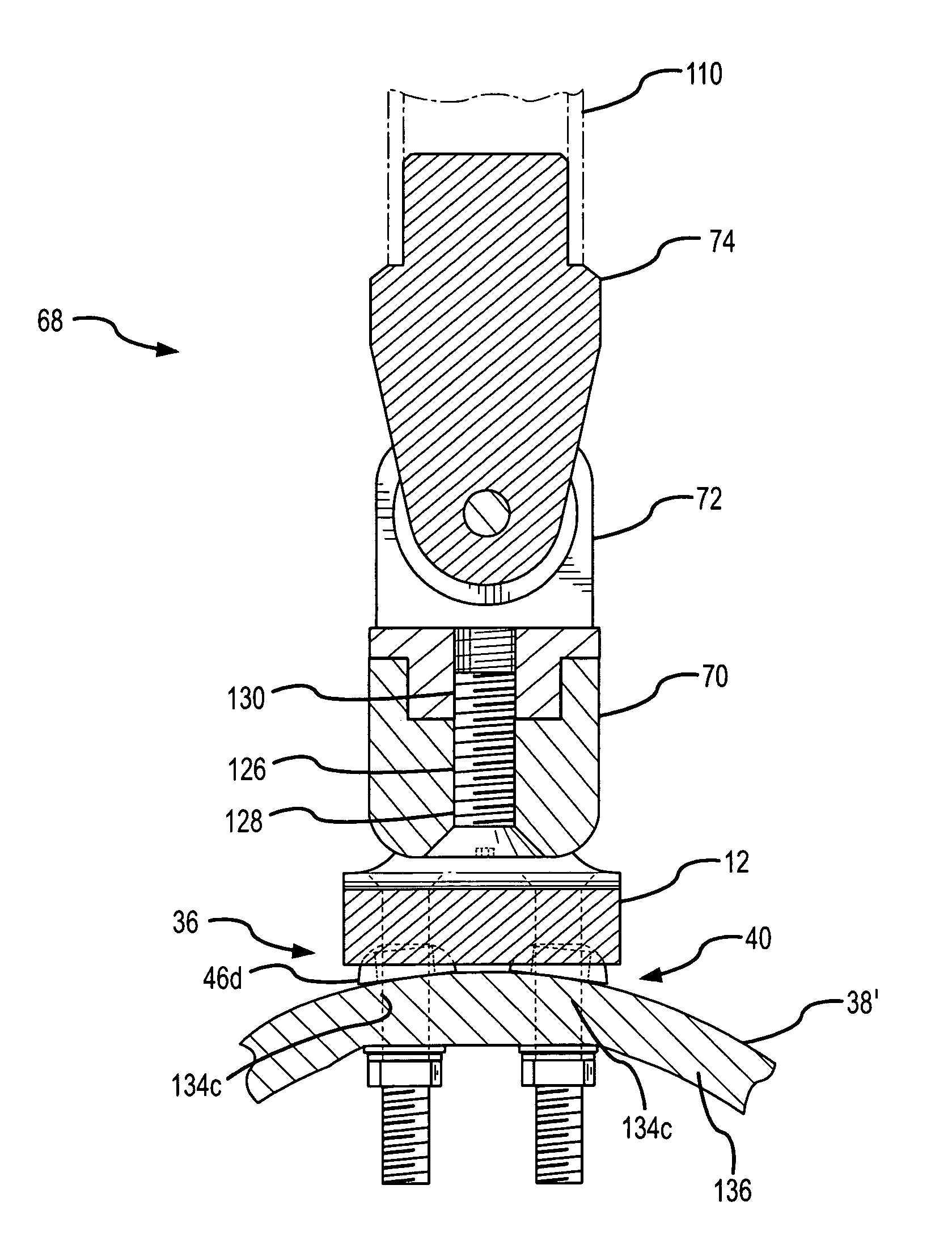
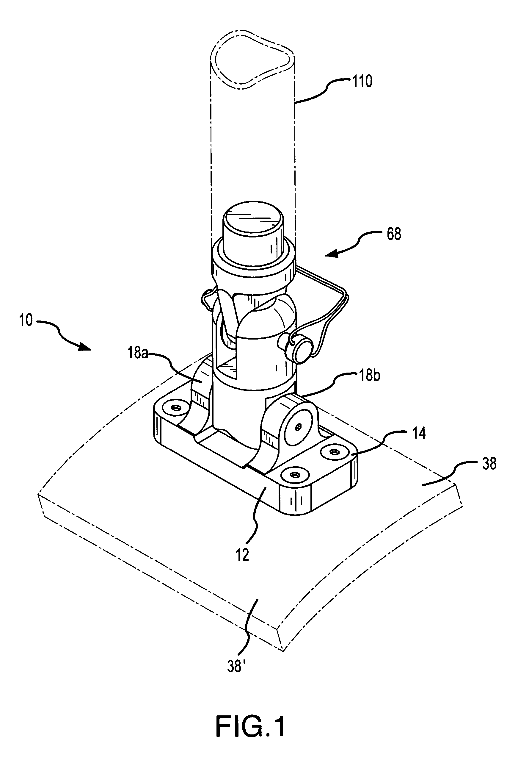
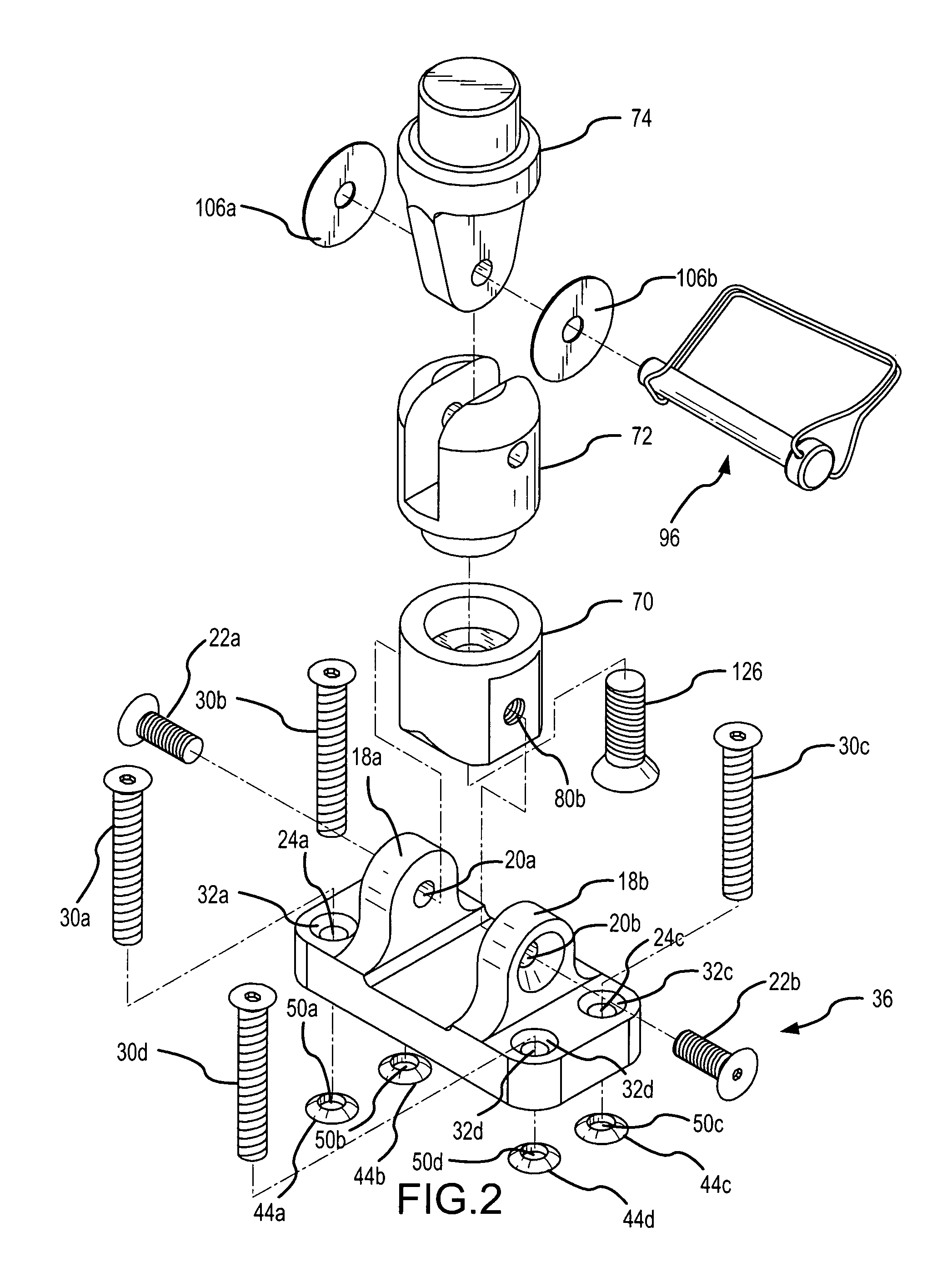
[0038]Briefly, the present invention provides a coupler. The coupler of the present invention includes a base formed monolithically with opposing yokes, means for mounting the base on a curved surface, a boom-swivel device removably positionable on the base, and a clevis mechanism slidably and demountably engageable with the boom-swivel device.

[0039]FIG. 1 illustrates the coupler of the present invention assembled and mounted on a curved surface. Referring initially, therefore, to FIG. 1, the coupler is shown and generally designated 10. As shown, coupler 10 includes a base 12. Base 12 is formed with an upper side 14 and a lower side 16 as best shown by cross-reference between FIGS. 1, 4 and 9a-9b. Lower side 16 of base 12 is substantially a flat planar surface. Base 12 also includes opposing yokes 18a,b. Opposing yokes 18a,b are formed monolithically in base 12, and in a preferred embodiment of the present invention, extend substantially at right angles from upper side 14 of base 1...


PUM


Abstract

A coupler for to which a shaft is attachable is provided. includes a base. The base is formed with an upper side and an lower side. The lower side is substantially a flat planar surface. Means are provided for mounting the base on a curved surface. A preferred means is one or more ball washer assemblies. In addition, the present invention includes a tub that is adjustably connectable to the base. A plug is provided that is repositionably attachable to the tub. In addition, a neck is provided. The neck is insertable into the plug. The neck also is formed to support a shaft. The invention includes a clevis mechanism that is slidably and demountably engageable with both the plug and the neck.

Description

FIELD OF THE INVENTION[0001]The present invention pertains generally to installing load-bearing shafts on variously shaped surfaces. More particularly, the new and useful invention claimed in this document pertains to a variably positionable coupler mountable on a curved surface and capable of securing a shaft in a variety of positions. The present invention is particularly, but not exclusively, useful for mounting a shaft that is part of a wakeboard tower on the curved surface of a boat hull.BACKGROUND OF THE INVENTION[0002]Myriad shafts are used and deployed to secure loads. The term “shaft” as used in this document includes at least non-exclusive items such as poles, handles, bars, pins, axle, rod and other shafts. While shafts are thought of as primarily cylindrical, the cross-sectional shape of a shaft is not a limitation of the present invention. Loads placed on a shaft may arise from a variety of forces, either alone or in combination. Sources for such forces may include wind...

Claims


Application Information

Patent Timeline
Patent Type & Authority Patents(United States)
IPC IPC(8): F16C11/00B63B17/00B63B35/81F16B43/00F16C11/06F16M11/12
CPCB63B35/815F16C11/06F16M11/10F16M11/2064F16M13/02F16M11/12F16B43/00Y10T403/32221Y10T403/32286F16C2326/30B63B34/60
Inventor TAYLOR, STEVE B.
Owner TAYLOR STEVE B
Why Eureka
Try Eureka