
Method and arrangement by a workover riser connection

Inactive Publication Date: 2008-02-26
BLAFRO TOOLS
View PDF13 Cites 42 Cited by
  • Summary
  • Abstract
  • Description
  • Claims
  • Application Information

AI Technical Summary

Benefits of technology

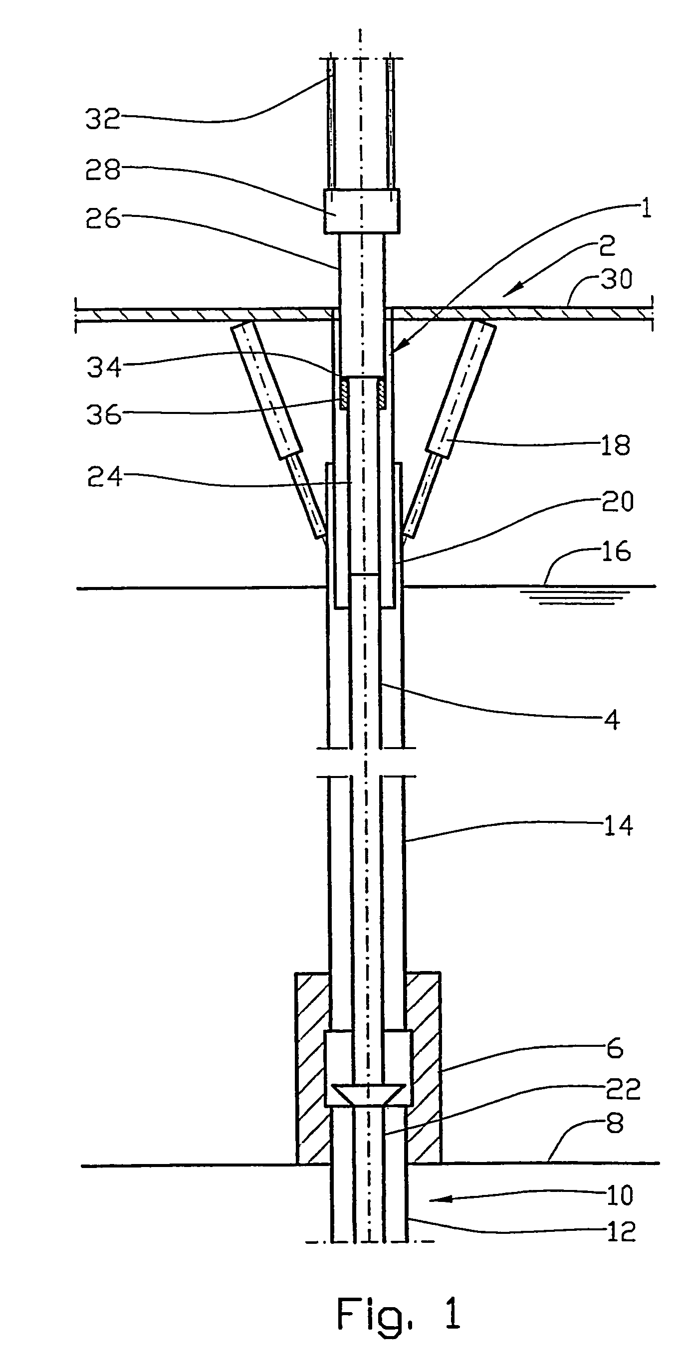
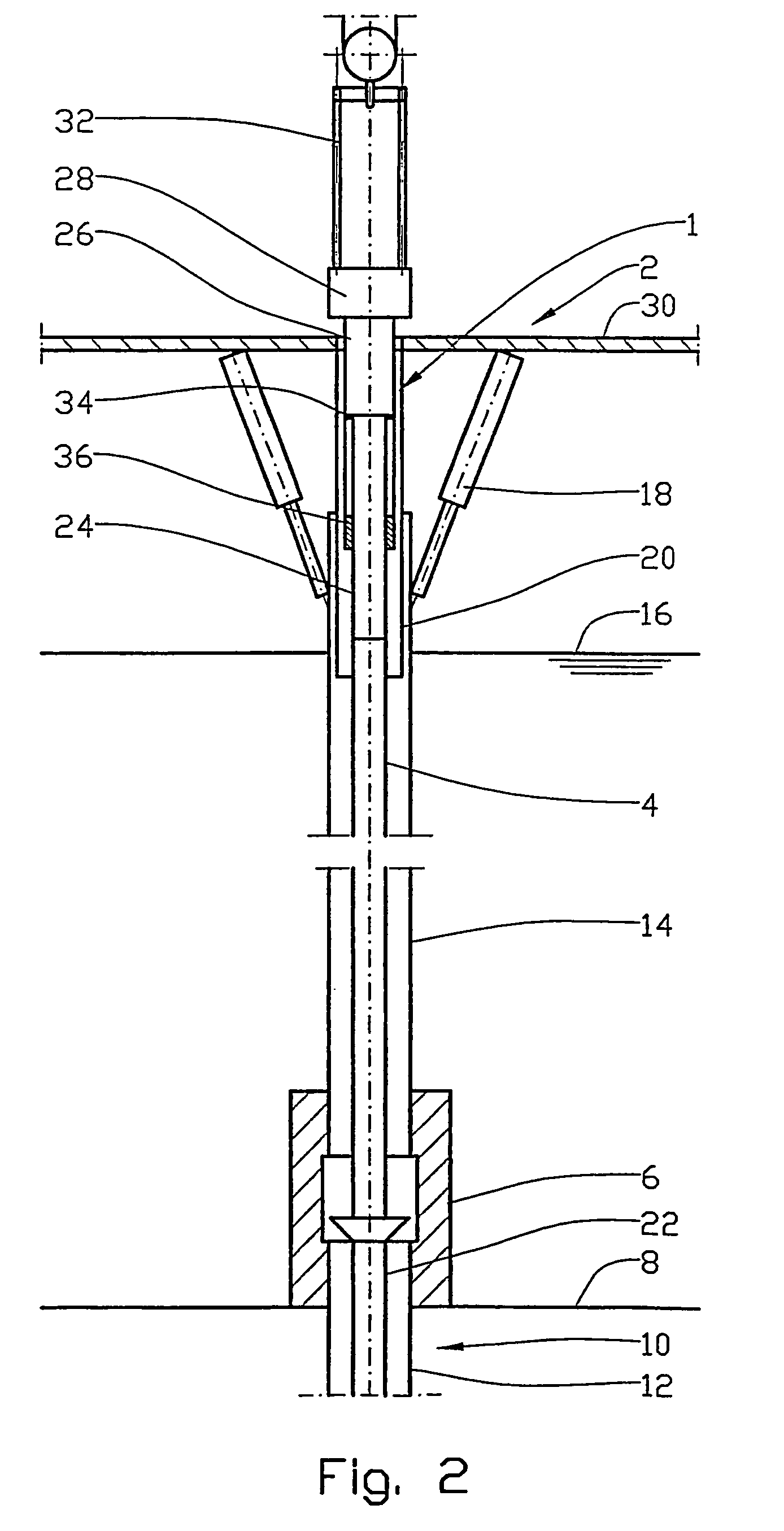
[0009]In order to be able to place the surface valves on the working deck during said operations, the workover riser is equipped with a telescoping, pressure-proof sliding connection. The sliding connection is disposed on the workover riser between the wellhead and the traveling block of the vessel and designed to telescope the sliding connection about its axial central position when the surface valves are immediately above the working deck. When the workover riser is to be pressurized, the telescoping sliding connection is extended to its limit of travel, and in this extended position it is designed to withstand the tensile forces that occur in workover risers of this type.

Problems solved by technology

As a result of the danger that exists of personnel getting caught in the surface valve during such work, existing regulations do not allow work at the surface valve when the relative motion exceeds 1.5 meters.
Clearly production is often interrupted in winter (windy periods) due to excessive heave motion.

Method used


Image

  • Method and arrangement by a workover riser connection
  • Method and arrangement by a workover riser connection
  • Method and arrangement by a workover riser connection

Examples


Embodiment Construction

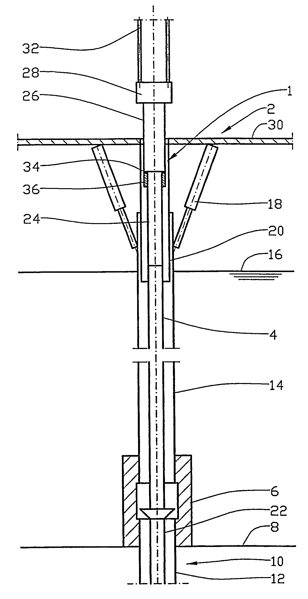
[0015]In the drawings, reference number 1 denotes a telescoping sealing sliding connection connected onto the workover riser 4 of a vessel 2. A wellhead 6 is arranged on the seabed 8 and connected to the casing 12 of a well 10. A riser 14 is connected to the wellhead 6, projecting up through the surface of the sea 16 and on up to where it is connected to the vessel 2 by means of a heave compensator device 18. A telescopic pipe 20 is connected to the vessel 2 and designed to be displaced in the riser 14.

[0016]A production tubing 22 is arranged in the well 10 and hung off in the wellhead 6. From the vessel, the workover riser 4 projects down to the wellhead 6, where the workover riser 4 is communicatingly connected to the production tubing 22.

[0017]The telescoping sliding connection 1 comprises a lower inner telescopic pipe 24 fixed to the workover riser 4 and an upper outer telescopic pipe 26 connected to a surface valve 28. The surface valve 28 is arranged over the working deck 30 o...


PUM


Abstract

A slip joint for a riser between a well and a floating petroleum installation, for example an oil platform. The slip joint includes, an outer pipe and an inner pipe, the pipes arranged to enable telescopic movement relative to one another in order to compensate for a change in distance between the sea bottom and the platform. The inner pipe is connected to a piston, the piston being operable in response to hydraulic pressure for inflicting a tensile force on riser. The outer diameter of the inner pipe is adapted to the diameter of outer pipe so as to form an annulus between the pipes. The piston is fixedly connected to inner pipe at or close to a downwardly directed end thereof, the annulus and the piston being subjected to hydraulic pressure. A protective sleeve is provided below the piston, which is slippingly arranged within outer pipe.

Description

FIELD OF THE INVENTION[0001]This invention regards a method of facilitating well operations from a vessel, in particular operations connected with well completion and well intervention, where use is made of a workover riser preferably equipped with surface valves, especially in connection with petroleum production. The invention also regards an arrangement for implementation of the method.SUMMARY OF THE INVENTION[0002]A common method of well completion is contingent upon a vessel equipped for the work operations in question being anchored or positioned over the well after the well has been drilled, cased and closed off. When the vessel has been positioned over the well, the well is opened and a wellhead comprising a number of valves and connecting pipes is lowered onto the seabed and connected to the casing. A riser is connected to the wellhead, projecting up through the sea to the vessel, where it is hung off in a heave compensator device designed to maintain tension in the riser d...

Claims


Application Information

Patent Timeline
IPC IPC(8): E21B7/12E21B17/01E21B17/07
CPCE21B17/01E21B17/07
Inventor BLAKSETH, OLAJOHNSEN
Owner BLAFRO TOOLS
Learn More