Memory card connector

a memory card and connector technology, applied in the direction of coupling device connection, coupling protective earth/shielding arrangement, instruments, etc., can solve the problems of heat dissipation, plastic material of the housing tends to shrink, and the connector housing deformation

Inactive Publication Date: 2008-02-26
MOLEX INC
View PDF8 Cites 12 Cited by
  • Summary
  • Abstract
  • Description
  • Claims
  • Application Information

AI Technical Summary

Benefits of technology

[0008]In the exemplary embodiment of the invention, the connector has an interior cavity for receiving a memory card. An insulating housing has a rear terminal-mounting section at the rear of the cavity. At least one longitudinal side wall section extends forwardly from one end of the rear section at one side of the cavity. The housing has a bottom surface for mounting on a circuit board, and the longitudinal side wall section has a top surface. A plurality of terminals are mounted on the rear terminal-mounting section and have contact portions for engaging contacts on the memory card. A metal shell covers at least a portion of the insulating housing and includes a cover plate overlying at least a portion of the longitudinal side wall section of the housing. An engaging structure includes an engaging projection on one of the cover plate of the metal shell or the top surface of the side wall section of the housing extending into an opening in the other of the cover plate or top surface to prevent relative movement therebetween in a plane generally parallel to the cover plate and top surface. There is a slight clearance between the engaging projection and the engaging opening to avoid creating residual stresses in the housing.

Problems solved by technology

The heat generated by these soldering processes often create problems in deforming the housing of the connector.
Specifically, when the plastic housing is cooled after a reflow soldering process, the plastic material of the housing tends to shrink because of the cooling, along with heat dissipation.
In fact, there is a possibility that the card-receiving cavity of the connector becomes contracted or narrowed and makes it impossible to insert the card thereinto.
Unfortunately, such approaches create further problems because the press-fit engagement between the engaging components create residual stresses in the plastic material of the housing.
In fact, when the side wall sections of the housing are made thinner in order to reduce the size and weight of the connector, such press-fit engagements can cause torsion and deflection of the side wall sections of the housing if not the entire body of the housing.

Method used


Image

  • Memory card connector
  • Memory card connector
  • Memory card connector

Examples


second embodiment

[0034]FIG. 9 shows an engaging structure, generally designated 78A. In this embodiment, an engaging projection in the form of an engaging tab 88 is stamped and formed out of an opening 88a in cover plate 70 of the metal shell. Engaging. projection or tab 88 is inserted into an engaging opening 90 in either one or both of the side wall sections 42 and / or 44. Again, a slight clearance 86 is maintained between engaging projection 88 and engaging opening 90 to avoid creating any residual stresses in the plastic material of the side wall section of the housing.

[0035]FIG. 10 shows a third embodiment of an engaging structure, generally designated 78B, which is similar to the second embodiment in FIG. 9. Again, an engaging projection or tab 88 is stamped and formed out of an opening 88a in cover plate 70 of the metal shell. The engaging projection or tab 88 is inserted into an engaging opening 90 in side wall section 42 and / or 44. A slight clearance 86 is maintained between the engaging tab...

first embodiment

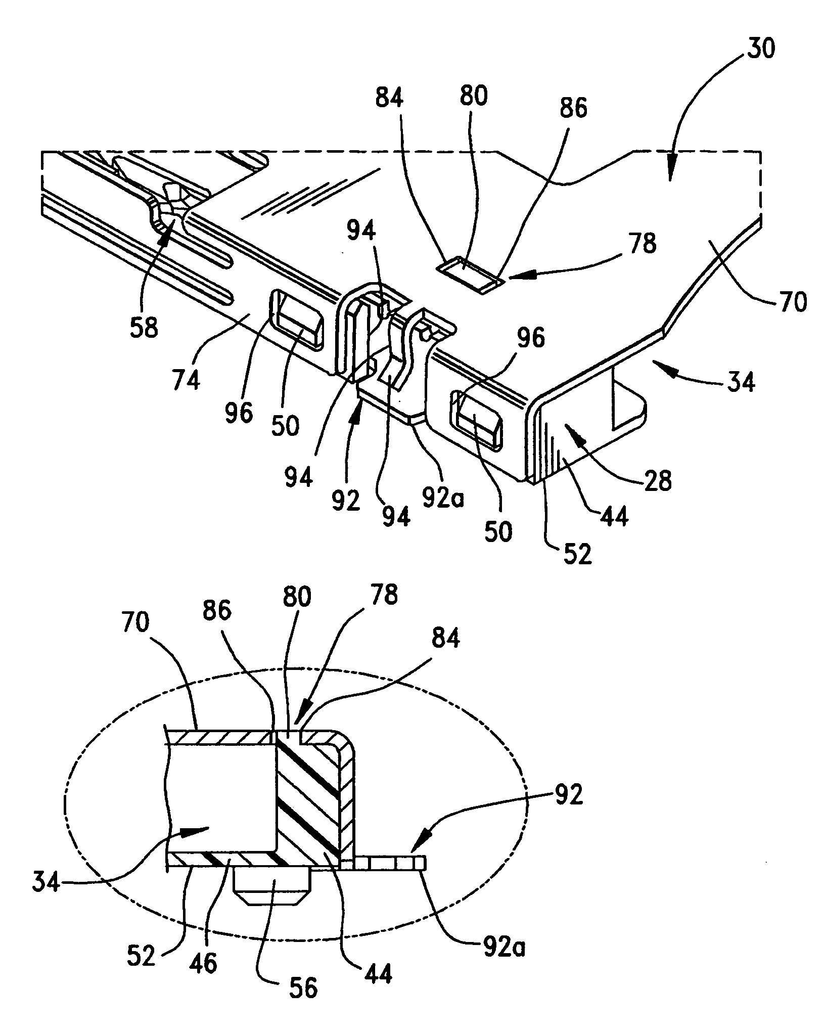
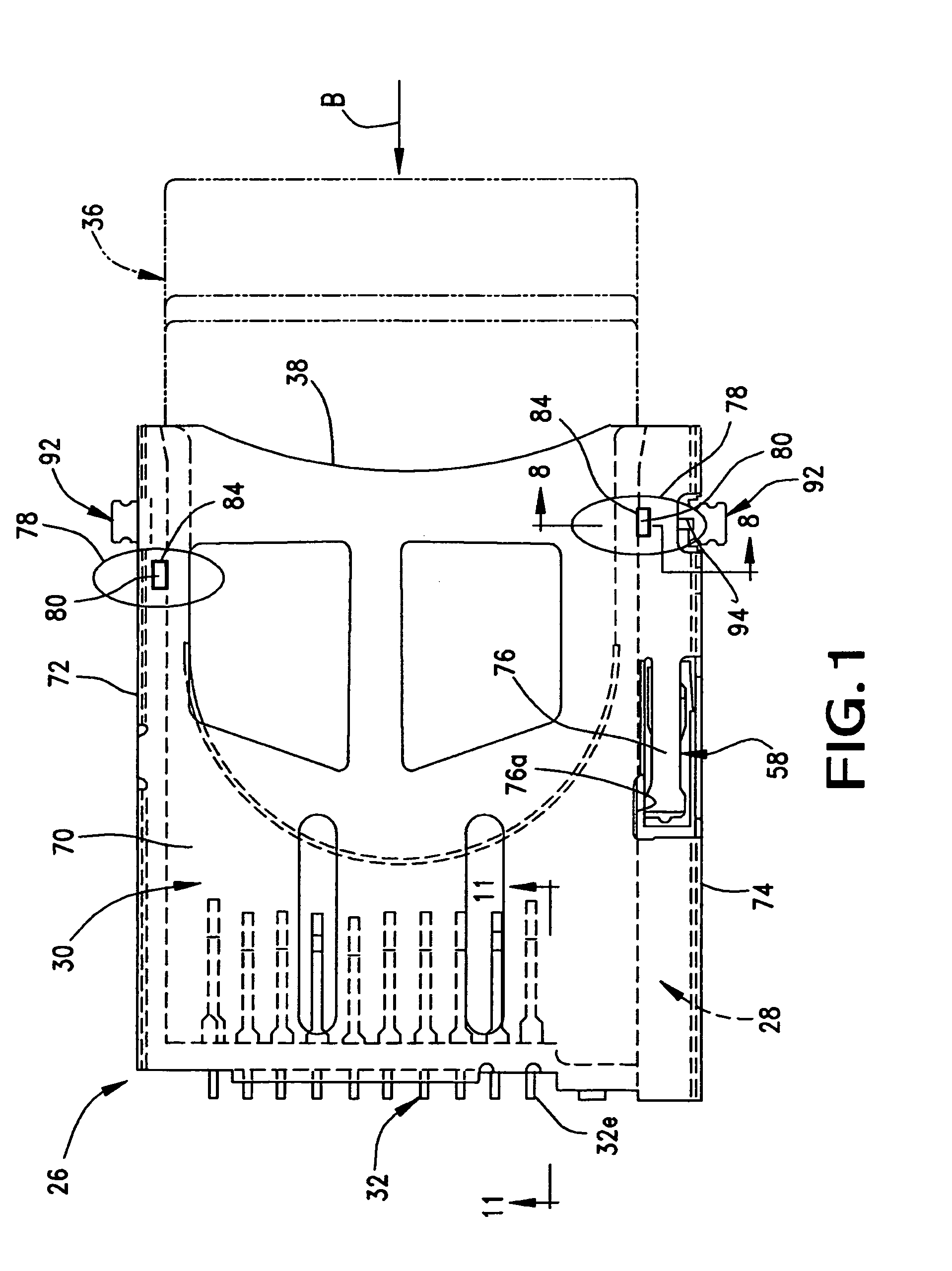
[0037]Lastly, FIG. 12 shows a modified form of a housing 28 which is L-shaped versus the U-shaped housing of FIG. 6. Like numerals have been applied in FIG. 12 for like components described above. In other words, the housing in FIG. 12 includes a rear terminal-mounting section 40, but only one side wall section 42 on which is mounted a card ejection mechanism 58. According to the invention, an engaging projection 80 projects upwardly from side wall section 42 near distal end 82 thereof. As with FIGS. 1-8, engaging projection 80 will project into an opening 84 in the cover plate of the metal shell, while maintaining a slight clearance between the engaging projection and the engaging opening.


PUM


Abstract

A memory card connector includes an interior cavity for receiving a memory card. An insulating housing has a rear terminal-mounting section and at least one longitudinal side wall section extending forwardly from one end of the rear section. A metal shell covers at least a portion of the insulating housing and includes a cover plate overlying at least a portion of the longitudinal side wall section of the housing An engaging structure includes an engaging projection on one of the cover plate of the metal shell or the top surface of the side wall section of the housing extending into an engaging opening in the other of the cover plate or top surface to prevent relative movement therebetween in a plane generally parallel to the cover plate and top surface. A slight clearance is provided between the engaging projection and the engaging opening to avoid creating residual stresses in the housing.

Description

FIELD OF THE INVENTION[0001]This invention generally relates to the art of electrical connectors and, particularly, to a memory card connector.BACKGROUND OF THE INVENTION[0002]Memory cards are known in the art and contain intelligence in the form of a memory circuit or other electronic program. Some form of card reader reads the information or memory stored on the card. Such cards are used in many applications in today's electronic society, including video cameras, digital still cameras, smartphones, music players, ATMs, cable television decoders, toys, games, PC adapters, multi-media cards and other electronic applications. Typically, a memory card includes a contact or terminal array for connection through a card connector to a card reader system and then to external equipment. The connector readily accommodates insertion and removal of the card to provide quick access to the information and program on the card. The card connector includes terminals for yieldingly engaging the con...

Claims


Application Information

Patent Timeline
Patent Type & Authority Patents(United States)
IPC IPC(8): H01R24/00
CPCG06K7/0021H01R43/0256
Inventor MATSUKAWA, JUNTOMITA, MITSUHIROMATSUMOTO, YASUYOSHI
Owner MOLEX INC
Why Eureka
Try Eureka