Method and apparatus for equalizing broadband chirped signal

a broadband chirped signal and equalization technology, applied in the field of equalization of chirped signals, can solve the problems of impedance mismatch at the interface between a connector and a wire, the signal component will need to have many taps, and be extremely long and complex

Inactive Publication Date: 2008-02-26
COBHAM DEFENSE ELECTRONICS SYST CORP
View PDF26 Cites 5 Cited by
  • Summary
  • Abstract
  • Description
  • Claims
  • Application Information

AI Technical Summary

Problems solved by technology

This is generally undesirable and requires equalization of the receive signal in order to compensate for such interference.
If the unwanted signal component has a wide bandwidth, such as would be the case for a chirped radar transmit signal, which might be swept over a very broad bandwidth, the necessary FIR filter to cancel such a signal component will need to have many taps and be extremely long and complex.
Thus, for instance, in a radar system, there may be an impedance mismatch at the interface between a connector and a wire, between any two pieces of equipment, and even at the interface between the metal surface of the antenna and the air.

Method used


Image

  • Method and apparatus for equalizing broadband chirped signal
  • Method and apparatus for equalizing broadband chirped signal
  • Method and apparatus for equalizing broadband chirped signal

Examples


Embodiment Construction

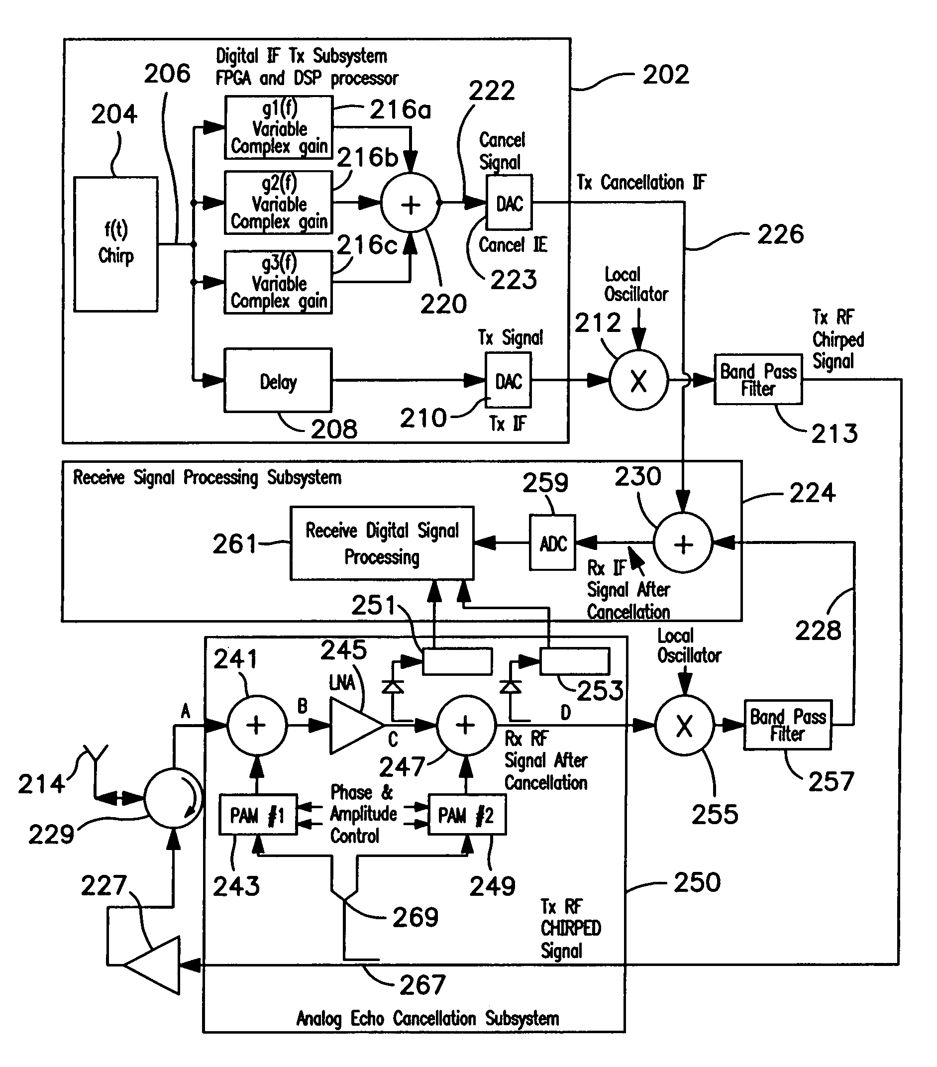
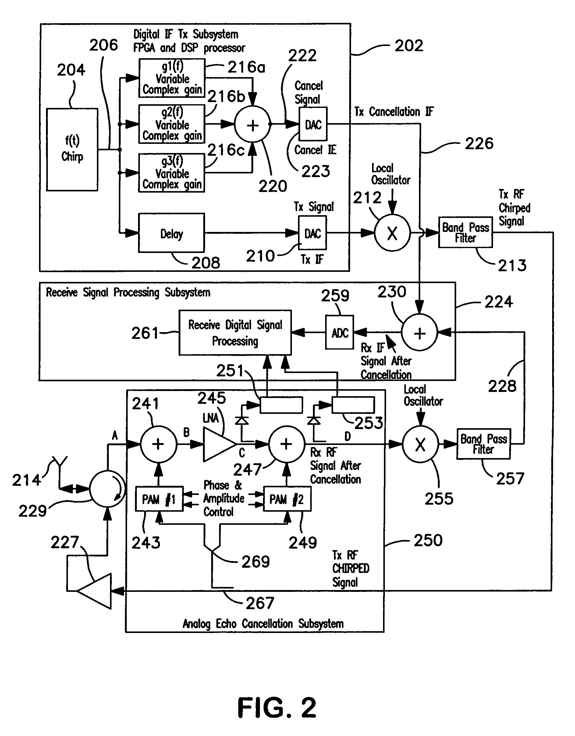
[0015]In accordance with the present invention, in order to generate a signal for canceling a known, unwanted chirped signal, a cancellation signal is generated using a single-term, variable, complex gain multiplier adapted to cancel the chirped signal only in its narrow instantaneous frequency range, rather than attempting to cancel it with a complex FIR or other filter that continuously compensates over the entire bandwidth of the chirped signal. The simple, narrowband cancellation signal is varied in amplitude and phase as a function of the frequency of the chirped transmit signal which it is intended to compensate. Since the signal that is to be cancelled is essentially a narrowband sinusoidal signal, but swept through a broad frequency range, the cancellation signal for the instantaneous transmit signal needs to be varied in both amplitude and phase in unison with the change in frequency of the transmit signal in order to accommodate gain and phase changes in the transmitted si...


PUM


Abstract

In order to generate a signal for canceling a chirped signal, a transmitter generates a cancellation signal along with the transmitted signal, using a single term variable complex gain multiplier adapted to cancel the chirped signal only at its instantaneous frequency, rather than attempting to cancel it with a complex FIR filter that works over the entire bandwidth of the chirped signal. The cancellation signal is varied in amplitude and phase as a function of the frequency of the chirped transmit signal for which it is intended to compensate. Since the signal that is to be cancelled is essentially sinusoidal but swept through a frequency range, the cancellation signal for the instantaneous transmit signal needs to be swept in both amplitude and phase in unison with the change in frequency of the transmit signal in order to accommodate gain and phase changes in the transmitted signal as a function of frequency. Particularly, the gain as well as the phase of the transmit signal generally will vary as a function of frequency due to limitations of the signal generation circuitry. Therefore, the cancellation signal must be varied in both amplitude and phase as a function of frequency. The necessary algorithm for changing the amplitude and / or phase of the cancellation signal as a function of frequency of the transmit signal can be readily determined by conventional techniques during a training session.

Description

FIELD OF THE INVENTION[0001]The present invention relates to equalization of chirped signals and the like.BACKGROUND OF THE INVENTION[0002]A chirped signal generally refers to a sinusoidal signal that varies in frequency over time, typically sweeping back and forth over a predetermined frequency range at a predetermined periodicity. Chirped signals are used, for instance, in radar applications. For instance, in radar, it is often desirable to generate a chirped transmit signal so that the delay between transmission of a wave and the return of the reflection of the wave off of a tracked object can be determined by measuring the frequency of a received reflected signal relative to the frequency of the contemporaneous transmitted signal.[0003]In at least one common form of radar, the same antenna is used to transmit an outgoing signal (waves) and to receive the resultant return signals reflected from objects in the path of the transmitted waves. Particularly, the transmitter is turned ...

Claims


Application Information

Patent Timeline
Patent Type & Authority Patents(United States)
IPC IPC(8): G01S7/35G01S13/00G01S7/36
CPCG01S7/34G01S13/282
Inventor STEWART, TODD ALAN
Owner COBHAM DEFENSE ELECTRONICS SYST CORP
Why Eureka
Try Eureka