Impedance matching method of pulse RF power supply and matching method of plasma equipment

A technology of radio frequency power supply and impedance matching, which is applied in the direction of plasma, circuit, discharge tube, etc., and can solve the problems of wafer plasma-induced damage, low matching accuracy, poor stability, etc.

Active Publication Date: 2015-12-30
BEIJING NAURA MICROELECTRONICS EQUIP CO LTD
View PDF10 Cites 19 Cited by
  • Summary
  • Abstract
  • Description
  • Claims
  • Application Information

AI Technical Summary

Problems solved by technology

[0005] The above-mentioned ICP equipment is used to etch the wafer. When the characteristic size of the etching process reaches 20nm and below, since the first radio frequency power supply 14 and the second radio frequency power supply 17 are continuous wave radio frequency power supplies, plasma-induced damage will be caused to the wafer. (PID), in order to avoid the generation of PID, then the first radio frequency power supply 14 and / or the second radio frequency power supply 17 adopts the pulsed radio frequency power supply, yet, there is the problem of poor stability and low matching precision to the impedance matching of the pulsed radio frequency power supply in existing

Method used


Image

  • Impedance matching method of pulse RF power supply and matching method of plasma equipment
  • Impedance matching method of pulse RF power supply and matching method of plasma equipment
  • Impedance matching method of pulse RF power supply and matching method of plasma equipment

Examples


Embodiment Construction

[0026] In order for those skilled in the art to better understand the technical solution of the present invention, the impedance matching method of the pulsed radio frequency power supply and the matching method of the plasma equipment provided by the present invention will be described in detail below with reference to the accompanying drawings.

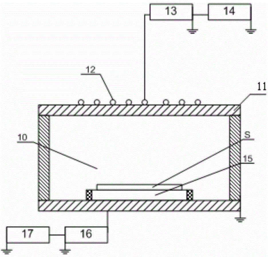
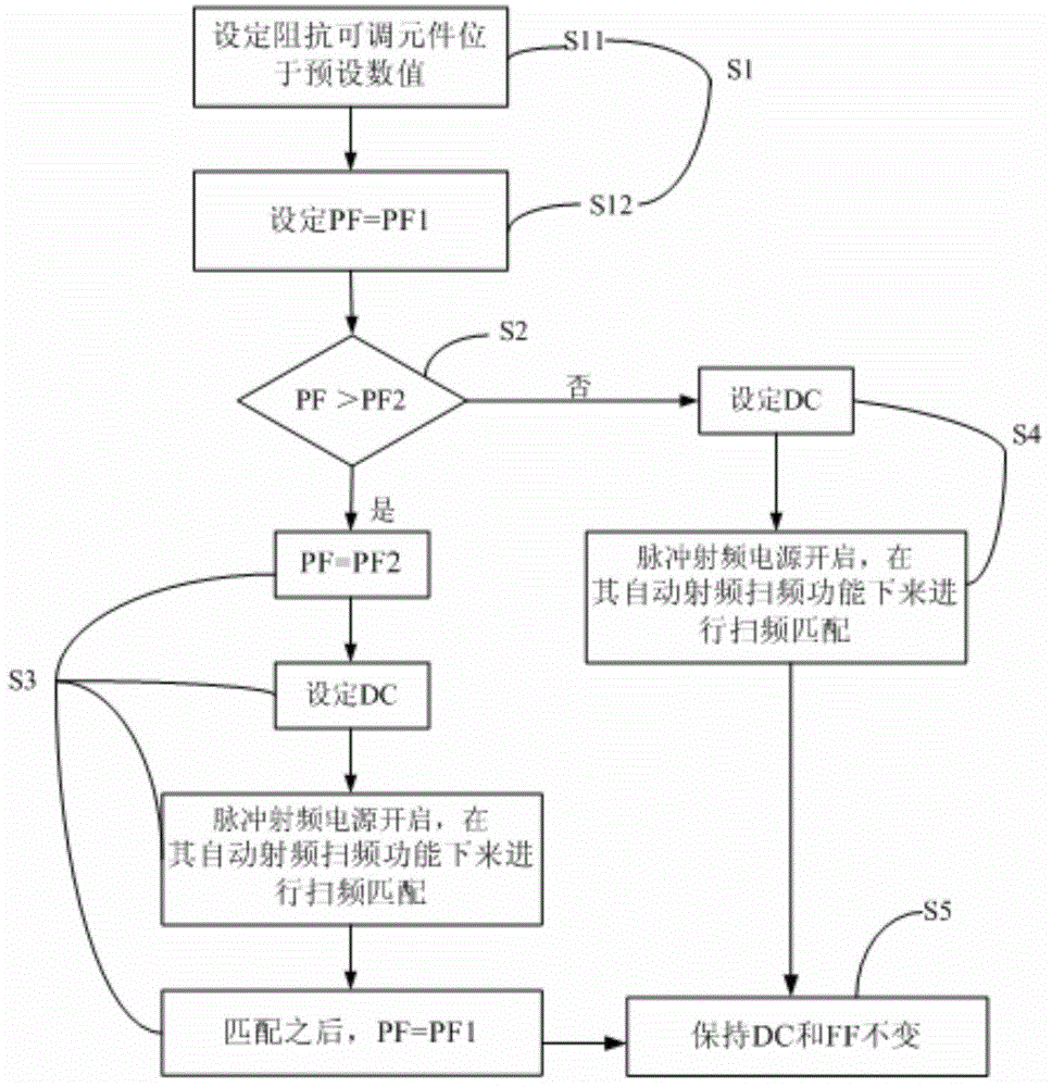
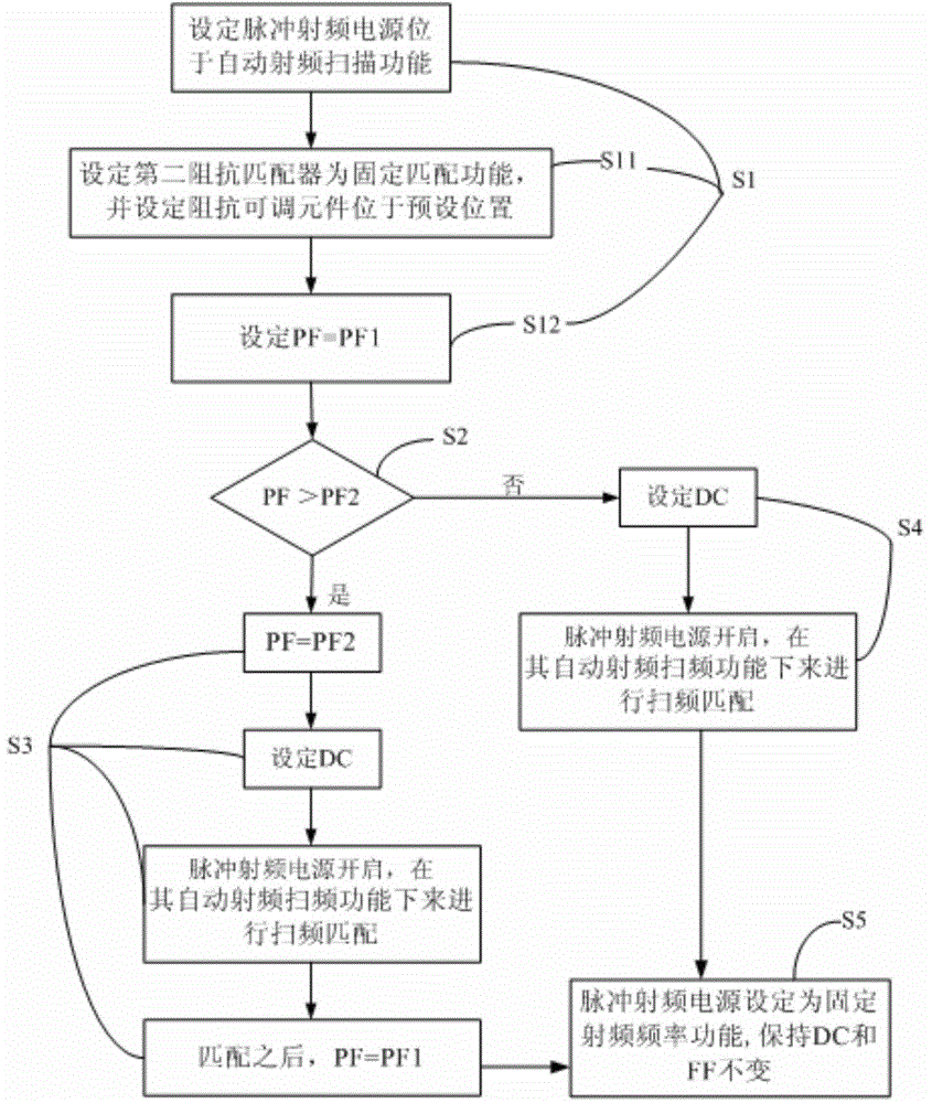
[0027] figure 2 It is a flow chart of the impedance matching method of the pulsed radio frequency power supply provided by the embodiment of the present invention. see figure 2 , the impedance matching method of the pulsed radio frequency power supply provided by the embodiment of the present invention, wherein the pulsed radio frequency power supply is connected with an impedance matcher, the impedance matcher includes an impedance adjustable element, the impedance adjustable element includes a variable capacitor, and the pulsed radio frequency power supply has an automatic radio frequency The frequency sweep function, specifica...


PUM


Abstract

The invention relates to an impedance matching method of a pulse RF power supply and a matching method of plasma equipment. The impedance matching method of the pulse RF power supply comprises a step of (S1) setting an impedance adjusting element at a preset value and setting the pulse frequency of the pulse RF power supply as a preset pulse frequency, (S2) judging whether the preset pulse frequency is larger than a pulse threshold frequency or not, and going to (S3) if so, (S3) allowing the pulse frequency of the RF power supply to be equal to the pulse threshold frequency, starting the pulse RF power supply, realizing sweep frequency matching under an automatic RF sweep frequency function, and switching the pulse frequency of the pulse RF power supply as a preset pulse frequency after matching, (S4) starting the pulse RF power supply, and realizing sweep frequency matching under the automatic RF sweep frequency function. According to the impedance matching method of the pulse RF power supply, the difficulty of realizing impedance matching by the RF power supply can be reduced, thus the matching precision and matching stability of the pulse RF power supply can be improved, and thus the stability of the process is improved.

Description

technical field [0001] The invention belongs to the technical field of semiconductor equipment manufacturing, and in particular relates to an impedance matching method of a pulsed radio frequency power supply and a matching method of plasma equipment. Background technique [0002] Plasma equipment is widely used in the preparation process of manufacturing integrated circuits IC or MEMS devices, mainly by means of RF power output RF power to excite the process gas to form plasma. [0003] Currently, plasma devices include capacitively coupled plasma (CCP) devices, inductively coupled plasma (ICP) devices, surface wave or electron cyclotron resonance plasma (ECR) devices. Among them, CCP equipment uses capacitive coupling to generate plasma. It has a simple structure, low cost, and is easy to generate large-area and uniformly divided plasma. It is suitable for the etching process of dielectric and other types of films; ECR equipment can High density plasma can be obtained und...

Claims


Application Information

Patent Timeline
Patent Type & Authority Applications(China)
IPC IPC(8): H01J37/32H05H1/46
Inventor 韦刚李东三
Owner BEIJING NAURA MICROELECTRONICS EQUIP CO LTD
Why Eureka
Try Eureka