
Solid-state image sensor efficiently utilizing its dynamic range and image pickup apparatus using the same

a solid-state image sensor and dynamic range technology, applied in the field of solid-state image sensors, can solve the problems of preventing the overall dynamic range from being efficiently available with the image sensor, affecting the efficiency of image signal processing, and reducing the size of individual photosensitive cells of the image sensor. , to achieve the effect of effectively using charge storage capacity, reducing the size of individual photosensitive cells and noise of image signals

Inactive Publication Date: 2008-02-26
FUJIFILM CORP
View PDF11 Cites 17 Cited by
  • Summary
  • Abstract
  • Description
  • Claims
  • Application Information

AI Technical Summary

Benefits of technology

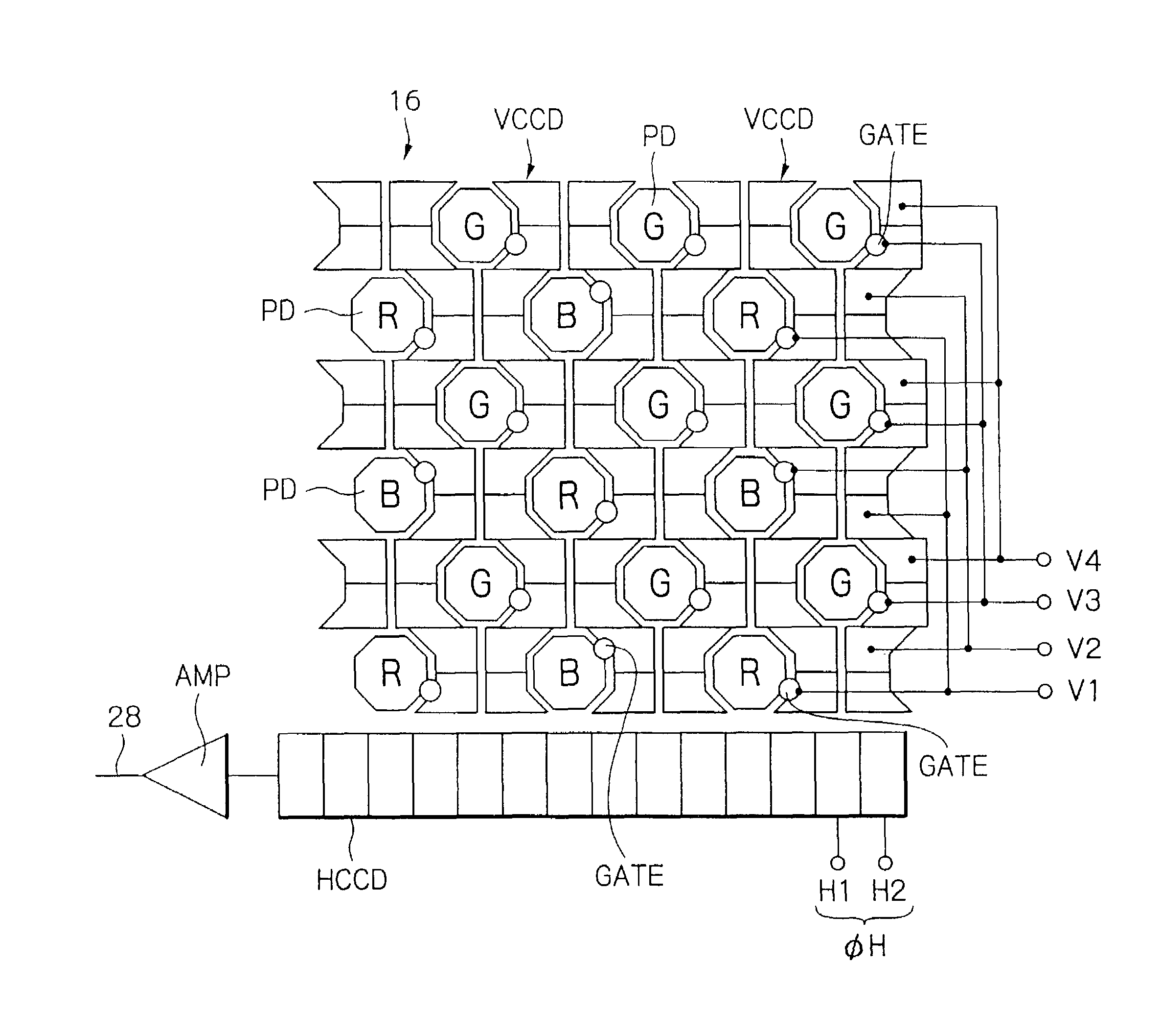
[0010]It is an object of the present invention to provide a solid-state image sensor capable of effectively using the charge storage capacity to the saturating extent, or dynamic range thereof, and reducing the size of the individual photosensitive cells as well as the noise of image signals, and an image pickup apparatus using the same.

Problems solved by technology

However, the problem with the camera is that the color balance of an image picked up is dependent on the color temperature of the light source used and other pickup conditions.
More specifically, the R, G and B filter segments of the color filter are different in spectral transmission characteristic and therefore in transmissivity for incident light of a particular color component, resulting in differences in sensitivity between the pixels of different colors of the image sensor.
The margin of the dynamic range thus provided, however, prevents the overall dynamic range from being efficiently available with the image sensor.
Moreover, the margin of the dynamic range makes it difficult to simply reduce the size of the individual photosensitive cells of the image sensor or to drive the cells with lower voltage.
Consequently, noise generated in the cells cannot be reduced.

Method used


Image

  • Solid-state image sensor efficiently utilizing its dynamic range and image pickup apparatus using the same
  • Solid-state image sensor efficiently utilizing its dynamic range and image pickup apparatus using the same
  • Solid-state image sensor efficiently utilizing its dynamic range and image pickup apparatus using the same

Examples


Embodiment Construction

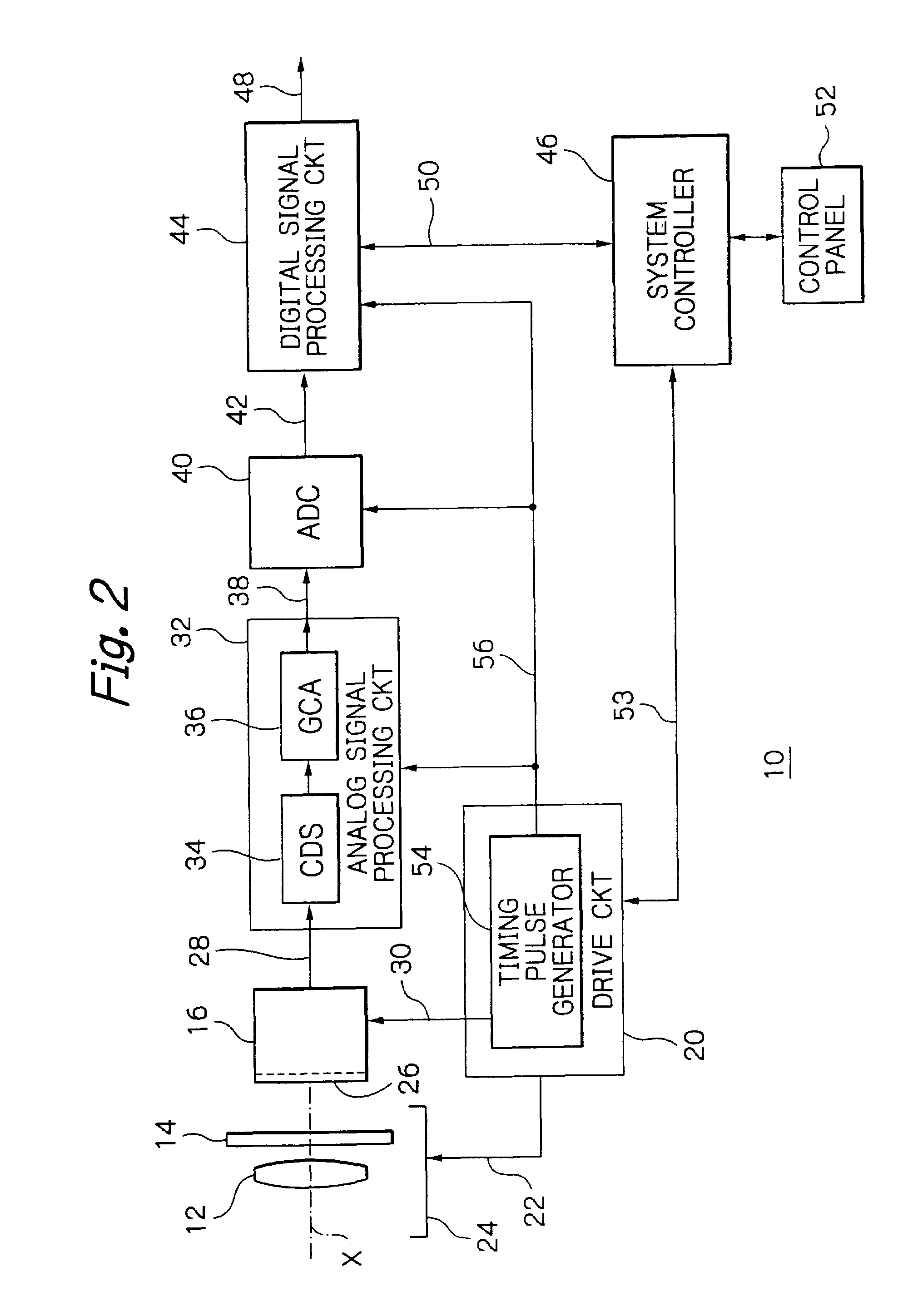
[0020]Referring to FIG. 2 of the accompanying drawings, an image pickup apparatus embodying the present invention is implemented as a digital camera by way of example. As shown, the digital camera, generally 10, includes an image pickup lens 12, a mechanical shutter 14 and a solid-state image sensor 16 sequentially arranged on an optical axis X in this order. An optical image captured from a scene is focused by the lens 12 on the array of photosensitive cells, not shown in FIG. 2, of the image sensor 16, and thereby converted to a moving picture or a still picture signal representative of the optical image. It is to be noted that part of the digital camera 10 not directly relevant to the understanding of the present invention is neither shown nor will be described. Signals appearing in the digital camera 10 are designated by reference numerals attached to connections on which they appear.

[0021]The camera 10 includes a drive circuit 20, which feeds drive signals to a drive mechanism ...


PUM


Abstract

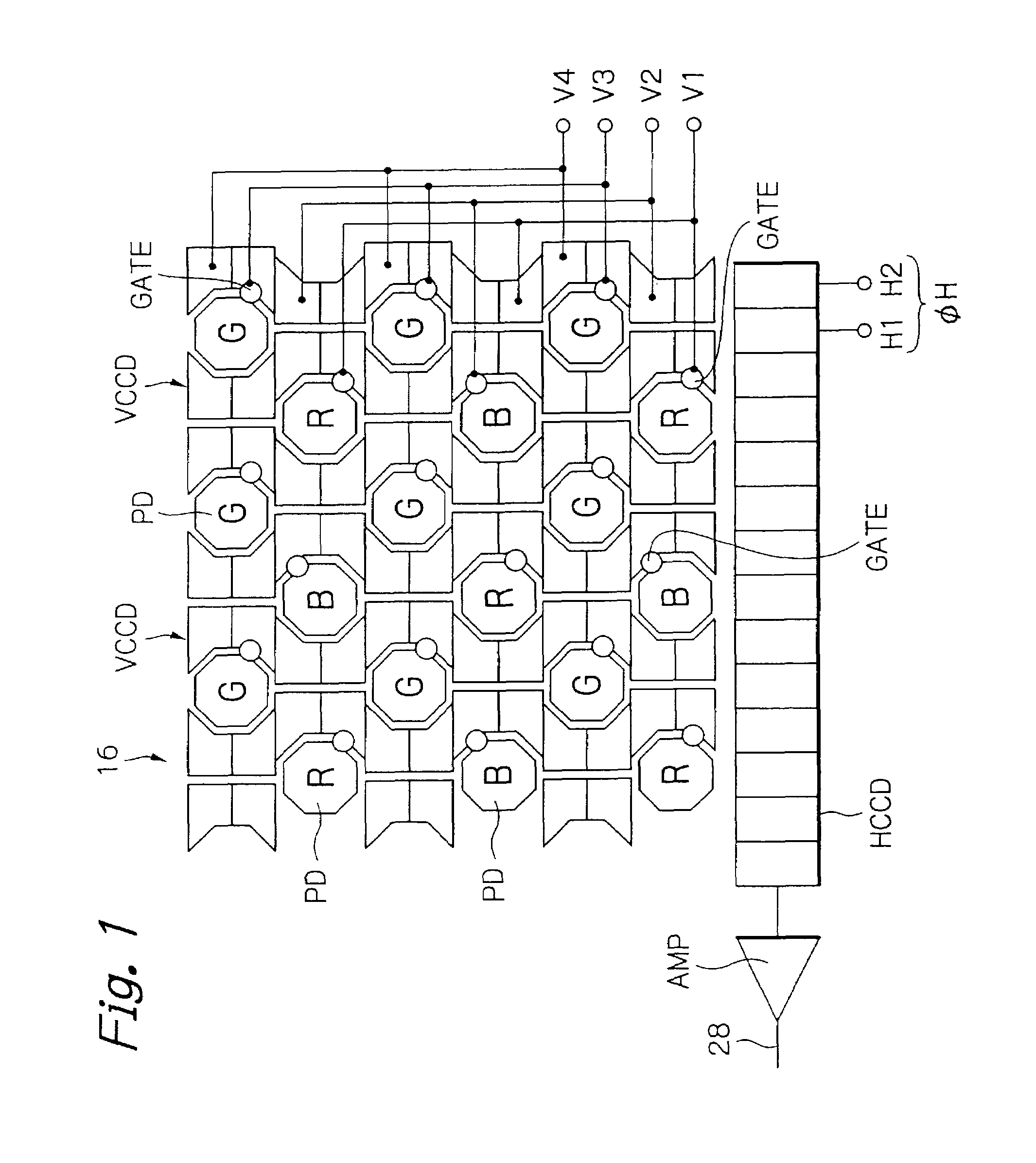
A solid-state image sensor includes photodiodes, which constitute pixels, shifted in position from each other and red (R), green (G) and blue (B) filter segments fitted on the photodiodes in a preselected pattern. R transfer gates, G transfer gates and B transfer gates each are connected to a particular vertical transfer electrode. Particular vertical drive pulses are fed to the electrodes to drive the transfer R, G and B transfer gates. Photodiode read pulses are applied to each of the electrodes at a particular timing on the basis of image signals output from the image sensor. Consequently, a signal charge generated in each photodiode is shifted to a particular vertical transfer path via the R, G or B transfer gate in accordance with color-by-color exposure time.

Description

BACKGROUND OF THE INVENTION[0001]1. Field of the Invention[0002]The present invention relates to a solid-state image sensor for outputting electric signals corresponding to amounts of light incident thereto and an image pickup apparatus using the same. More particularly, the present invention relates to a solid-state image sensor with a color filter fitted thereon.[0003]2. Description of the Background Art[0004]Today, a digital camera of the type using a solid-state image sensor configured to transform an optical image captured from a scene to electric image signals representative of the image is extensively used as an image pickup apparatus. This type of camera includes a digital signal processing circuit for processing digital image signals converted from the electric image signals. The digital image signals are subjected to various kinds of correction and then stored into a memory card or similar storage mounted on the camera.[0005]The image sensor is implemented as, e.g. a singl...

Claims


Application Information

Patent Timeline
Patent Type & Authority Patents(United States)
IPC IPC(8): H04N3/14H01L27/148H04N23/12H04N25/00
CPCH01L27/14868H04N3/1525H04N3/1575H04N9/045H04N2209/045H04N23/673H04N25/53H04N25/134
Inventor ODA, KAZUYA
Owner FUJIFILM CORP
Learn More