
Detecting sync patterns for optical media

Inactive Publication Date: 2008-02-26
MARVELL ASIA PTE LTD
View PDF1 Cites 1 Cited by
  • Summary
  • Abstract
  • Description
  • Claims
  • Application Information

AI Technical Summary

Benefits of technology

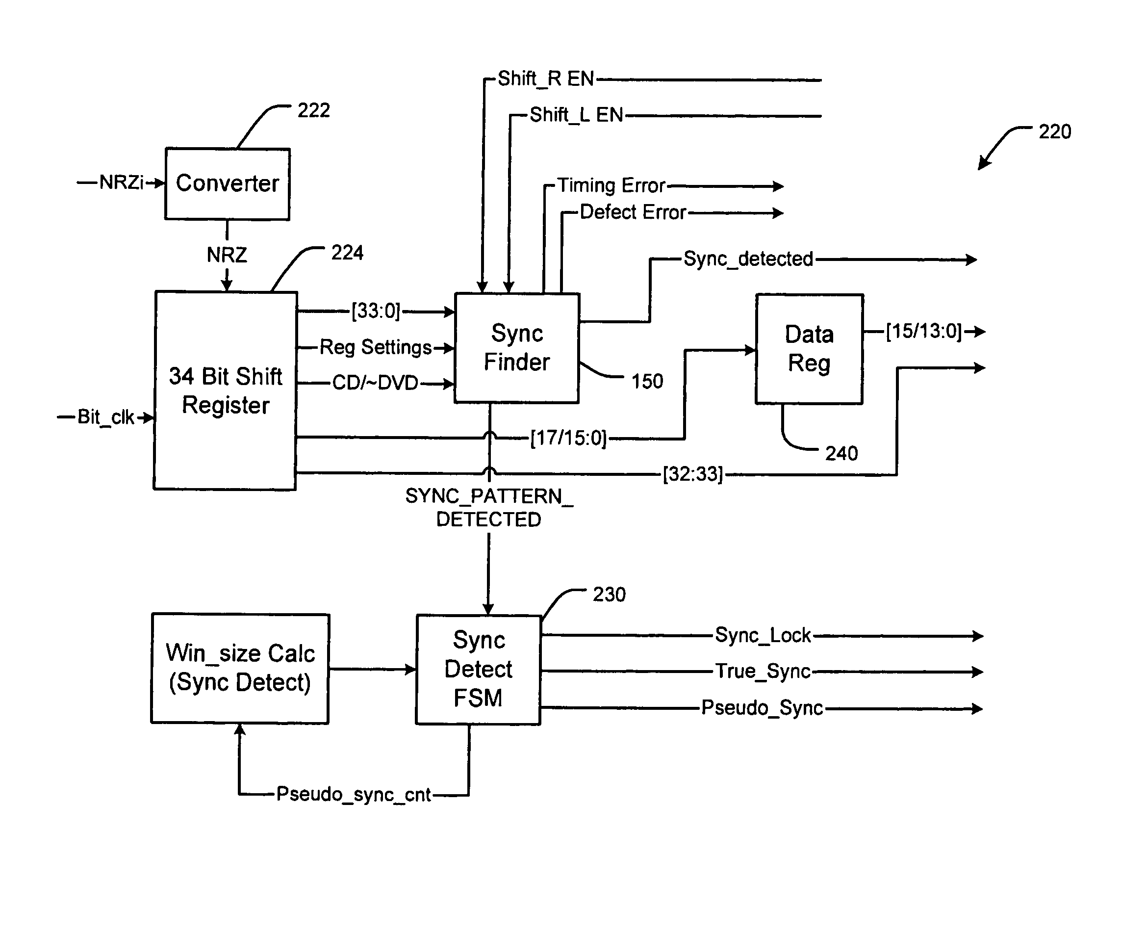
[0009]In other features, N is greater than one. The sync finder module verifies the sync pattern based in part on the verified signal. The pulse jitter detect module generates a second signal when remain

Problems solved by technology

Defect errors may occur due to scratches, dirt and / or other materials on the optical media.
Defect errors may alter the reflectivity of the laser light, which adversely impacts the NRZI converted signal that is generated by the optical sensor.
As a result, the NRZI converted signal may include errors.
In some situations, the defect errors may cause the sync detector circuit to fail to detect a sync pattern, which may cause the corresponding data block to be lost.
This kind of shifting pattern will make it more difficult to identify a proper sync pattern.
In some circumstances, a faulty sync pattern may be created that looks very similar to a sync pattern carrying defect errors.

Method used


Image

  • Detecting sync patterns for optical media
  • Detecting sync patterns for optical media
  • Detecting sync patterns for optical media

Examples


Embodiment Construction

[0026]The following description of the preferred embodiment(s) is merely exemplary in nature and is in no way intended to limit the invention, its application, or uses. For purposes of clarity, the same reference numbers will be used in the drawings to identify similar elements. As used herein, the term module refers to an application specific integrated circuit (ASIC), an electronic circuit, a processor (shared, dedicated, or group) and memory that execute one or more software or firmware programs, a combinational logic circuit, and / or other suitable components that provide the described functionality.

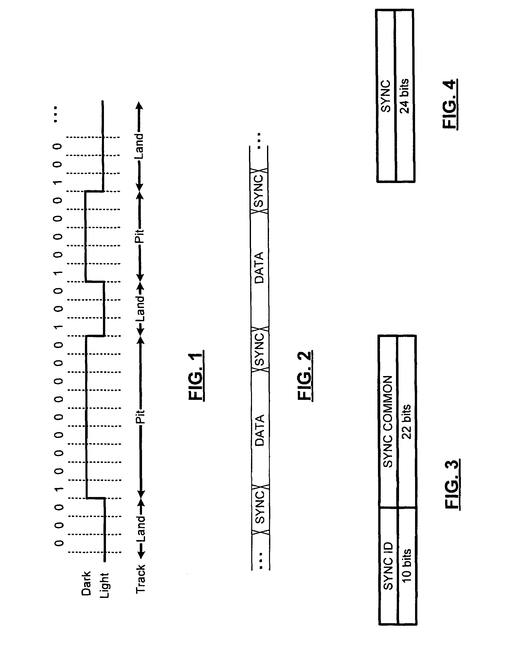
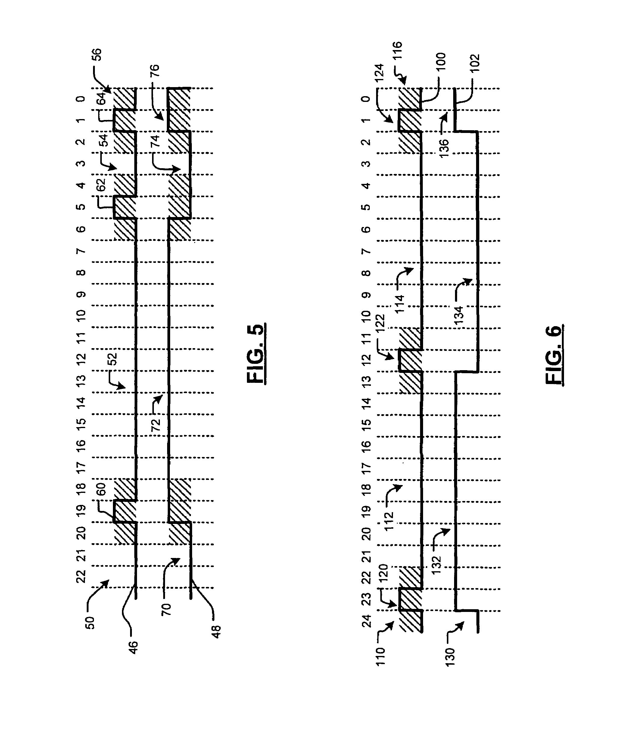
[0027]Referring now to FIGS. 3 and 4, for DVDs that are compliant with European Computer Manufacturers Association (ECMA)-267 (for DVD-Read-Only), ECMA-337 (DVD+RW) and ECMA-338 (DVD-RW) (which are hereby incorporated herein by reference), the sync pattern includes 32 bits. There are 10 sync identification (ID) bits, which may vary depending upon the application, and 22 sync common bi...


PUM


Abstract

A sync finder module for an optical medium playback device that generates a bit stream including sync patterns and data blocks comprises a pulse jitter detect module that receives the sync pattern, which includes a plurality of transitions each having a desired position in the sync pattern, that selects actual N-bit segments of the sync pattern at the desired positions and that compares the actual N-bit segments to at least one expected N-bit segment. A pulse verifying module communicates with the pulse jitter detect module and generates a verified signal if the expected N-bit segments match the actual N-bit segments.

Description

FIELD OF THE INVENTION[0001]The present invention relates to optical media playback devices, and more particularly to sync pattern detection in optical media playback devices.BACKGROUND OF THE INVENTION[0002]Optical media such as compact discs (CDs) and digital versatile discs (DVDs) store data that is read back optically. CDs typically include a substrate that is made of plastic. For pre-recorded CDs, the substrate may be impressed during manufacturing with microscopic bumps that are arranged as a continuous spiral track of data. The bumps correspond to pits (from the opposite side) and lands are located between adjacent pits. A layer such as aluminum may be formed on the substrate to cover the bumps. A protective layer such as an acrylic may also be applied over the aluminum layer.[0003]A DVD typically includes several layers. For pre-recorded DVDs, each layer may be impressed during manufacturing with microscopic bumps that are arranged as a spiral track of data. A reflective lay...

Claims


Application Information

Patent Timeline
IPC IPC(8): G11B7/00
CPCG11B20/10222G11B20/1217G11B2020/1287G11B2220/2545G11B2220/2562
Inventor LEE, WOOI KEAN
Owner MARVELL ASIA PTE LTD
Learn More