Sensor using ultra thin waveguides and optical fibers

a technology of optical fibers and waveguides, applied in the field of sensors, can solve the problems of high cost of multi-gas optical sensor systems, inability to use conventional optical fibers for sensing sections without major modification, and toxins may become chemical agents. achieve the effect of high efficiency

Inactive Publication Date: 2008-02-26
HONEYWELL INT INC
View PDF18 Cites 32 Cited by
  • Summary
  • Abstract
  • Description
  • Claims
  • Application Information

AI Technical Summary

Benefits of technology

[0011]In another exemplary embodiment, an apparatus is provided for an optical resonant sensor for sensing one or more contaminant particles in an environment, the optical sensor comprising a light source operable to emit light of tunable frequency, a mirror mounted on a substrate, an optical fiber coil, and a detector. The optical fiber coil has a first end and a second end; each positioned adjacently to the mirror and fastened to the substrate, such as by fastening in v-grooves. The mirror and the optical fiber coil form an optical resonator, i.e. the mirror directs light into the first end of the fiber, the light propagates through the fiber coil exiting through the second end of the fiber. The mirror directs a large fraction of the light emerging from the second end into the first end. The optical fiber is designed such that a portion of its evanescent field extends into, and interacts with, the environment. The mirror is preferably slightly transmissive such that light is coupled from the light source into the resonator with high efficiency when the light source frequency is tuned to the resonance frequency of the resonator, formed by the mirror and the optical fiber coil. The detector is positioned such that it detects the fraction of light energy not dissipated in the optical resonator.

Problems solved by technology

While these man-made chemical and environmental toxins may provide beneficial qualities when used properly, these toxins may become chemical agents if wrongly used.
This method of detecting substances typically uses relatively large monitored equipment that is not typically amenable to situations where portable monitoring devices are needed.
All-purpose, multi-gas optical sensor systems have been found to be very expensive, primarily because of the cost associated with the various light sources needed to illuminate a sensor or sensor array with light of the appropriate spectral bandwidth; that is, containing the large range of wavelengths needed to stimulate transitions in all the substances of interest.
In addition, conventional optical fibers cannot be used for the sensing section without major modification, in that the light's electric field does not extend out into the environment, meaning that does it not interact significantly with the environment in which the sensor resides.
Because of the light source power and spectral requirements, and because of the filter requirements, the cost, weight and volume are significant in prior art systems, which can limit the use of these systems in portable sensor applications or other environments in which a light weight or compact monitoring system is needed or desired, but a highly accurate sensor is required.

Method used


Image

  • Sensor using ultra thin waveguides and optical fibers
  • Sensor using ultra thin waveguides and optical fibers
  • Sensor using ultra thin waveguides and optical fibers

Examples


Embodiment Construction

[0021]The following detailed description of the invention is merely exemplary in nature and is not intended to limit the invention or the application and uses of the invention. Furthermore, there is no intention to be bound by any theory presented in the preceding background of the invention or the following detailed description of the invention.

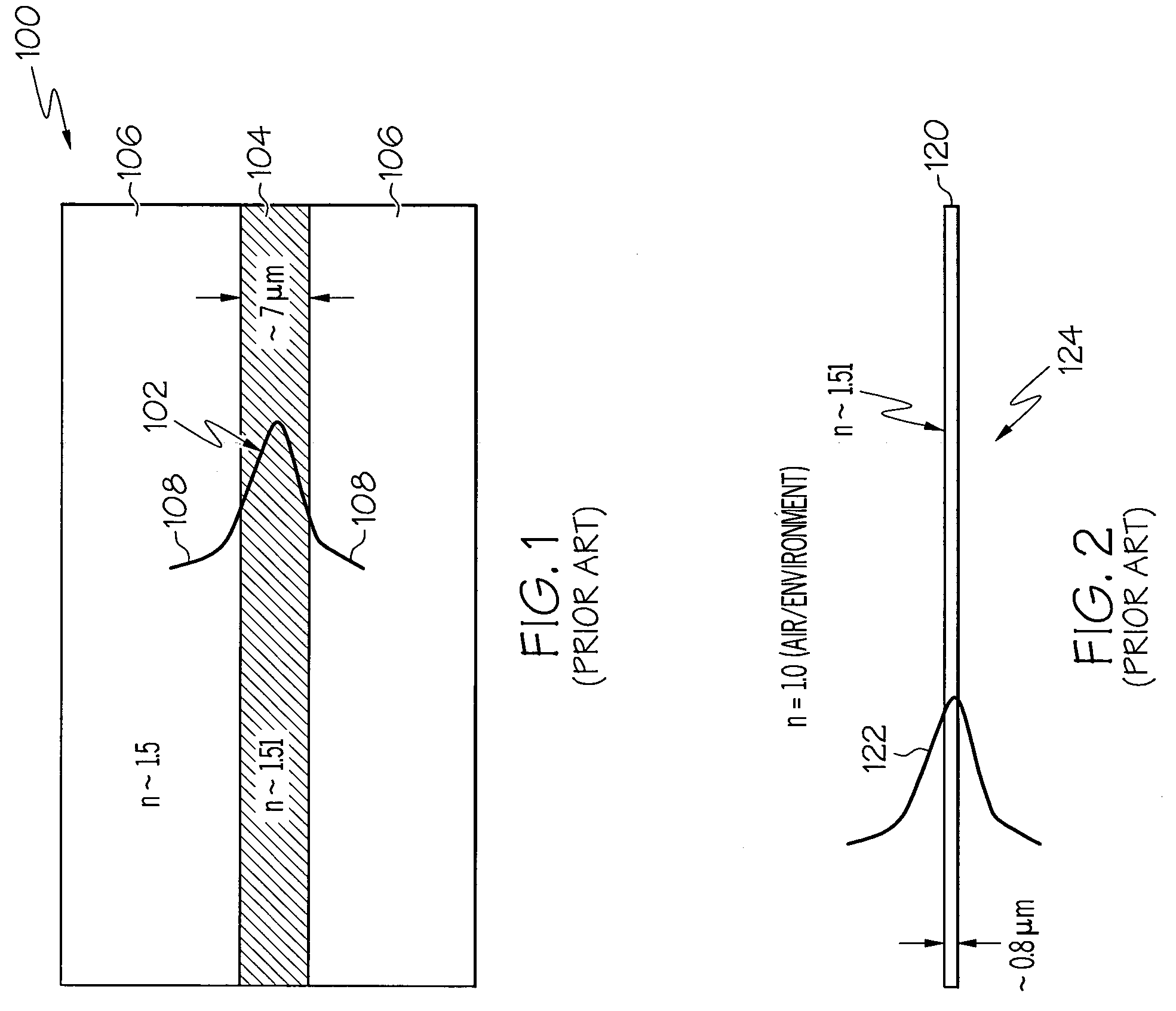
[0022]Referring to the drawings, illustrated in FIG. 1 is a conventional optical fiber 100 having a lightwave 102 depicted as traveling there through. In conventional fibers, signal-to-noise limitations have presented a problem in that a lightwave 102 traveling within fiber 100 does not interact strongly with the environment in which optical fiber 100 resides. Conventional optical fiber 100 is comprised of a glass material and includes at a central portion thereof, a core region 104. Core region 104 is generally formed of a doped glass material having an index of refraction that is higher than an index of refraction of a glass material 106 s...


PUM


Abstract

Methods and apparatus are provided for detecting one or more contaminant particles in an environment with an optical sensor. The sensor includes at least one optical waveguide in a resonant arrangement and a light source positioned in an environment in which the presence of a contaminant particle is sought to be determined. The at least one optical waveguide is of a diameter that an evanescent tail of the lightwave extending there through extends into the environment and is reactive to at least one contaminant particle in the surrounding environment. A detector is positioned to receive light indicative of the sharpness of the optical resonance lineshape of the optical resonator at a pre-selected optical wavelength. The detected information determines the specific contaminant particle in the environment and the concentration of the contaminant particle in the environment.

Description

FIELD OF THE INVENTION[0001]The present invention generally relates to sensors, and more particularly relates to chemical and biological sensors using ultra thin waveguides and optical fibers.BACKGROUND OF THE INVENTION[0002]In recent years, growing sophistication of terrorist threats to homeland and abroad makes awareness-of chemical and biological substances, including chemical and environmental toxins and biohazardous materials, of great importance. This awareness brings about a need for the accurate sensing and monitoring of these types of substances, especially those that may be present as air-borne particles / molecules and are dangerous to humans. The desired level of sensing sensitivity is that which provides for the accurate sensing of various chemical and biological substances at levels that are considered potentially dangerous, while preventing false alarms for levels of materials that are not considered potentially dangerous.[0003]Biohazardous materials are defined as thos...

Claims


Application Information

Patent Timeline
Patent Type & Authority Patents(United States)
IPC IPC(8): G02B6/00G02B6/02
CPCB82Y20/00G01N21/552G02B6/107G01N21/7703G01N21/7746G01N21/94G01N2021/7783G01N2201/0873G01N2201/088
Inventor SANDERS, GLEN A.
Owner HONEYWELL INT INC
Why Eureka
Try Eureka