Scalable functionality windows in a display unit

a display unit and functionality technology, applied in the field of scalable functionality windows shown in, can solve the problems of limited information displayed by the driver of an agricultural working machine, and achieve the effects of reducing the amount of effort required by the driver, saving costs, and improving the readability of the display uni

Inactive Publication Date: 2008-02-26
CLAAS SELBSTFAHRENDE ERNTEMASCHINEN GMBH
View PDF16 Cites 49 Cited by
  • Summary
  • Abstract
  • Description
  • Claims
  • Application Information

AI Technical Summary

Benefits of technology

[0005]Due to the fact that opening at least one additional functionality window causes an open window to be zoomed, the driver of the agricultural working machine is able to view a large amount of different information visualized in the functionality windows without the driver having to change or exit the current basic viewing window.
[0023]The fact that functionality windows can be hidden or displayed automatically reduces the amount of effort required by the driver and ensures a reliable supply of information.

Problems solved by technology

The disadvantage of a display structure of this type is the fact that the driver of an agricultural working machine is limited in terms of the information displayed—the driver is only shown the operating state or the out-of-operation state of the working units shown.

Method used


Image

  • Scalable functionality windows in a display unit
  • Scalable functionality windows in a display unit
  • Scalable functionality windows in a display unit

Examples


Embodiment Construction

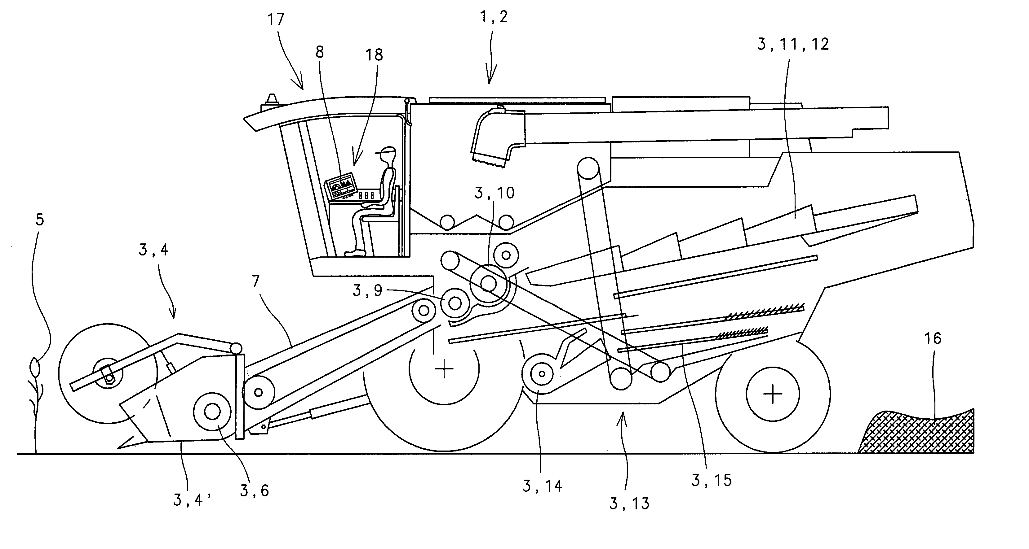
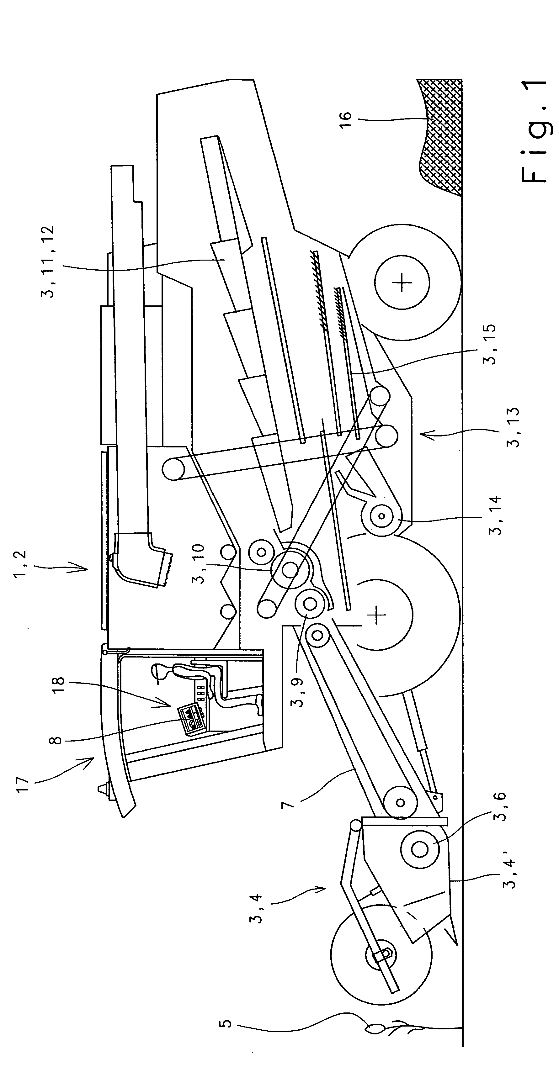
[0030]FIG. 1 shows an agricultural working machine 1 configured as a combine harvester 2, and its different working units 3. A header 4 is located in the front region of combine harvester 2. Header 4 picks up crops 5, cuts them and transfers them via a feed device 6 to downstream feed rake 7. Via feed rake 7, crops 5 are transferred in a known manner to the threshing devices. In this case, the threshing devices are composed of a first cylinder 9 and a second, downstream cylinder 10 assigned thereto.

[0031]To further separate the grain, the stream of material is conveyed to different separating devices 11 such as a tray-type shaker 12, and to different cleaning devices 13 composed substantially of a fan 14 and cleaning sieves 15, before the straw is ejected out of the back of combine harvester 2 and deposited on the ground to form a swath 16.

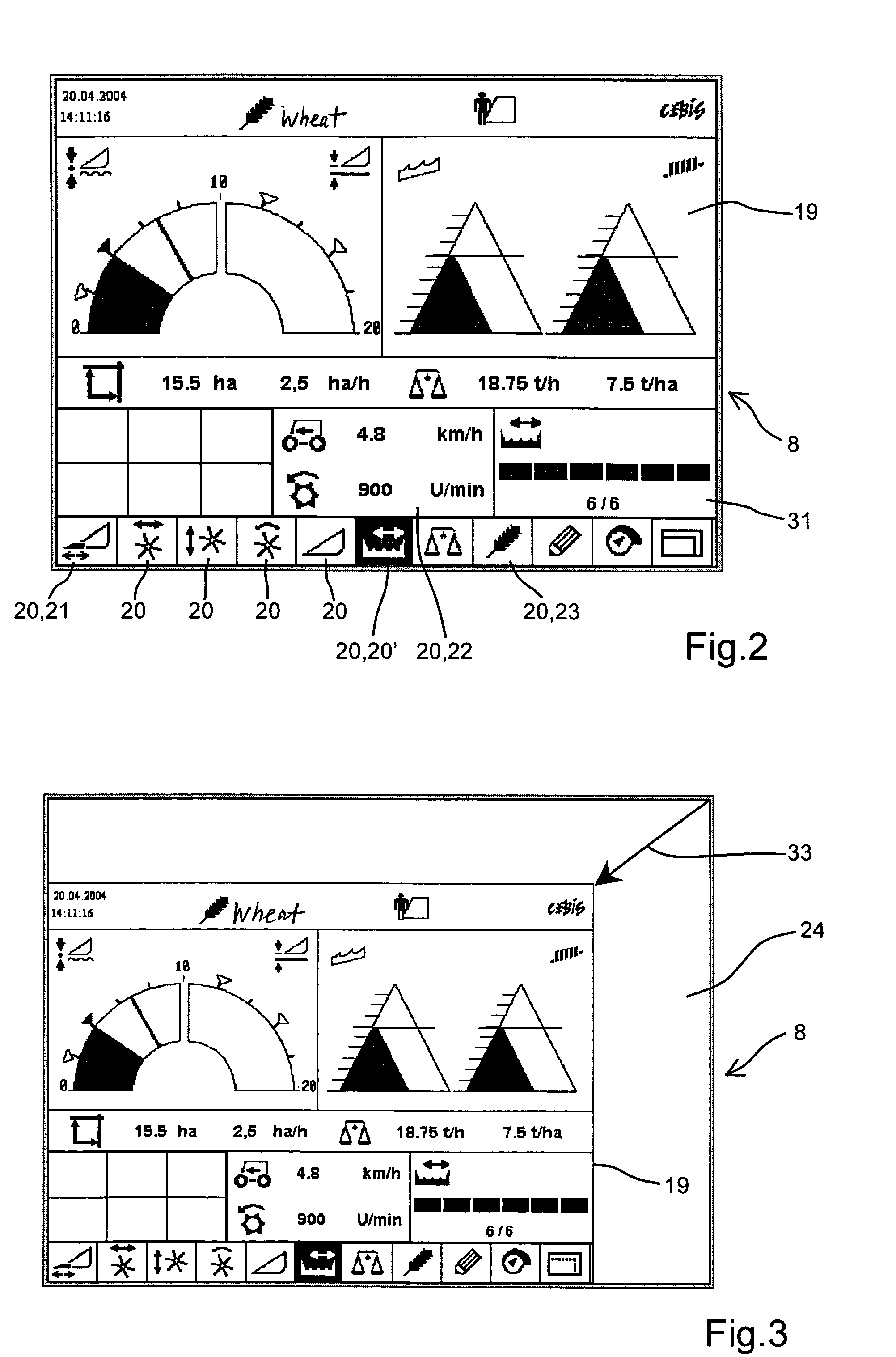
[0032]At a terminal 18 located in driver's cab 17, the driver of combine harvester 2 can enter settings for the different working units 3, such a...


PUM


Abstract

An agricultural working machine has at least one working unit, a driver's cab; at least one display unit provided in the driver's cab and having a basic electronic viewing screen for showing a plurality of machine and / or crop parameters stored in different functionality windows, the at least one display unit being assigned to the at least one working unit, the at least one display unit with the basic electronic viewing screen and the different functionality windows being formed so that when at least one additional functionality window is open, an open functionality window is zoomed.

Description

BACKGROUND OF THE INVENTION[0001]The present invention relates to the scalability of functionality windows shown in a display unit of a terminal integrated in an agricultural working machine.[0002]Publication DE 198 05 133 A1 discloses an electronic display and / or operating device with a display and status display fields, in the case of which the use of certain symbols makes it possible for the operating state or out-of-operation state of different working units to be displayed in the same display field. According to the invention, the out-of-operation state of a working unit is indicated, e.g., by the symbol of a line passing through the particular working unit, the line being located above the symbol provided. On the other hand, the operating state of a working unit is indicated, e.g., when a display assigned to the symbol provided illuminates. In this manner, no additional symbols are used to display the operating state or out-of-operation state. Additional symbols would reduce t...

Claims


Application Information

Patent Timeline
Patent Type & Authority Patents(United States)
IPC IPC(8): G05B13/02
CPCA01D41/127A01F15/08
Inventor DIEKHANS, NORBERT
Owner CLAAS SELBSTFAHRENDE ERNTEMASCHINEN GMBH
Why Eureka
Try Eureka