High pressure reinforced rubber hose swage or crimped coupling and method of attachment

a technology of reinforced rubber and hoses, which is applied in the direction of hose connections, joints with sealing surfaces, pipe-joints, etc., can solve the problems of reinforcement pulling (or tear) away from the rubber hose, and achieve the highest possible lock, extend the range of diameter and pressure applications, and extend the number of reinforcing plys

Inactive Publication Date: 2008-03-04
BALDWIN & LOKE
View PDF30 Cites 48 Cited by
  • Summary
  • Abstract
  • Description
  • Claims
  • Application Information

AI Technical Summary

Benefits of technology

[0029]The inner stem is first preferably expanded internally within the hose so that the stem grooves move slightly into the bore of the hose. The high points or flutes will move into the bore of the hose and exert a force against the inner most reinforcing plys. Care must be taken in designing the height of the flutes so that when the flutes move into the tube, they will not overstress the inner carcass and reinforcement. Unlike earlier art that used internal expansion to SEAL the internal diameter of the rubber hose to the stem and compress the hose into the ferrule, this device uses internal expansion to help first cause the reinforcement plys to ease into alignment with the lands and nodes of the ferrule and the flutes and grooves of the stem: after which the ferrule is swaged. This action means that, during ferrule swaging, the internally expanded stem will assist both the innermost reinforcement ply(s) and outermost reinforcement ply(s), remember that plys occur in pairs, into a tightly compressed wave pattern bound between the ferrule and stem.
[0030]The outer ferrule is then swaged onto the reinforcement to firmly attach the coupling to the hose. The swaging operation is done deliberately so that the bond between the reinforcing wire and rubber inside (1st carcass) is maintained. Thus, the ferrule lands are driven down into the reinforcement. As the compressing action of the swaging operation proceeds, the waved lands and flutes cause the metal reinforcement, tube and 1st carcass to “roll” or wave into the nodes of the ferrule and grooves of the stem passing over the lands of the ferrule and flutes of the stem resulting in the highest possible lock between the swaged end connector and the overall hose.
[0031]The invention assures that the local market distributor may custom manufacture reinforced rubber hose assemblies, using swaged end connections that meet or exceed the strength the hose. The invention extends the range of diameter and pressure applications for swaged hose and extends the number of reinforcing plys that may be held by such connectors particularly cable plys. Further the instant device works with rotary grade C, D and E hoses as well as other high pressure hose. It interacts well with multiple ply spiral cable reinforcement, multiple ply wire reinforcement, fabric and other reinforcement methods. It reduces or eliminates stress points in the reinforcing cable, wire plys or such. Finally, the invention will accept some hidden defects (a cable out of line or reinforcing off center) often found in reinforced rubber (elastomer) hose.
[0032]In overall summary, the instant invention utilizes a sinusoidal wave-like lock within a ferrule and stem to lock the reinforcement plys and the hose into the end connector by compressing the hose and reinforcement between the waved ferrule and waved stem. Stress and strain on the reinforcement and the tendency for the reinforcement to tear (or pull away) from the rubber hose is minimized by carefully reducing the relative axial displacement between the ferrule and stem that always occurs during the attachment operation. The relative axial displacement is minimized by using high tensile strength steels, minimum un-attached clearances between the hose and end connector, and careful design of the node, lands grooves and flutes to cause a sine like wave while minimizing the radial thickness of the stem and ferrule at the critical cross-sections and considering the resulting strength of the attached fitting.

Problems solved by technology

It is known in the prior art that the relative axial movement between the ferrule and the stem during a swaging (or crimping) operation causes stress and strain on the reinforcement and can cause the reinforcement to pull (or tear) away from the rubber hose.

Method used


Image

  • High pressure reinforced rubber hose swage or crimped coupling and method of attachment
  • High pressure reinforced rubber hose swage or crimped coupling and method of attachment
  • High pressure reinforced rubber hose swage or crimped coupling and method of attachment

Examples


Embodiment Construction

[0057]In order to understand the instant invention and how it is a substantial improvement over the current art, it is necessary to understand the structure and properties of reinforced rubber hose and the prior art of swaging metal couplings onto reinforced rubber hoses.

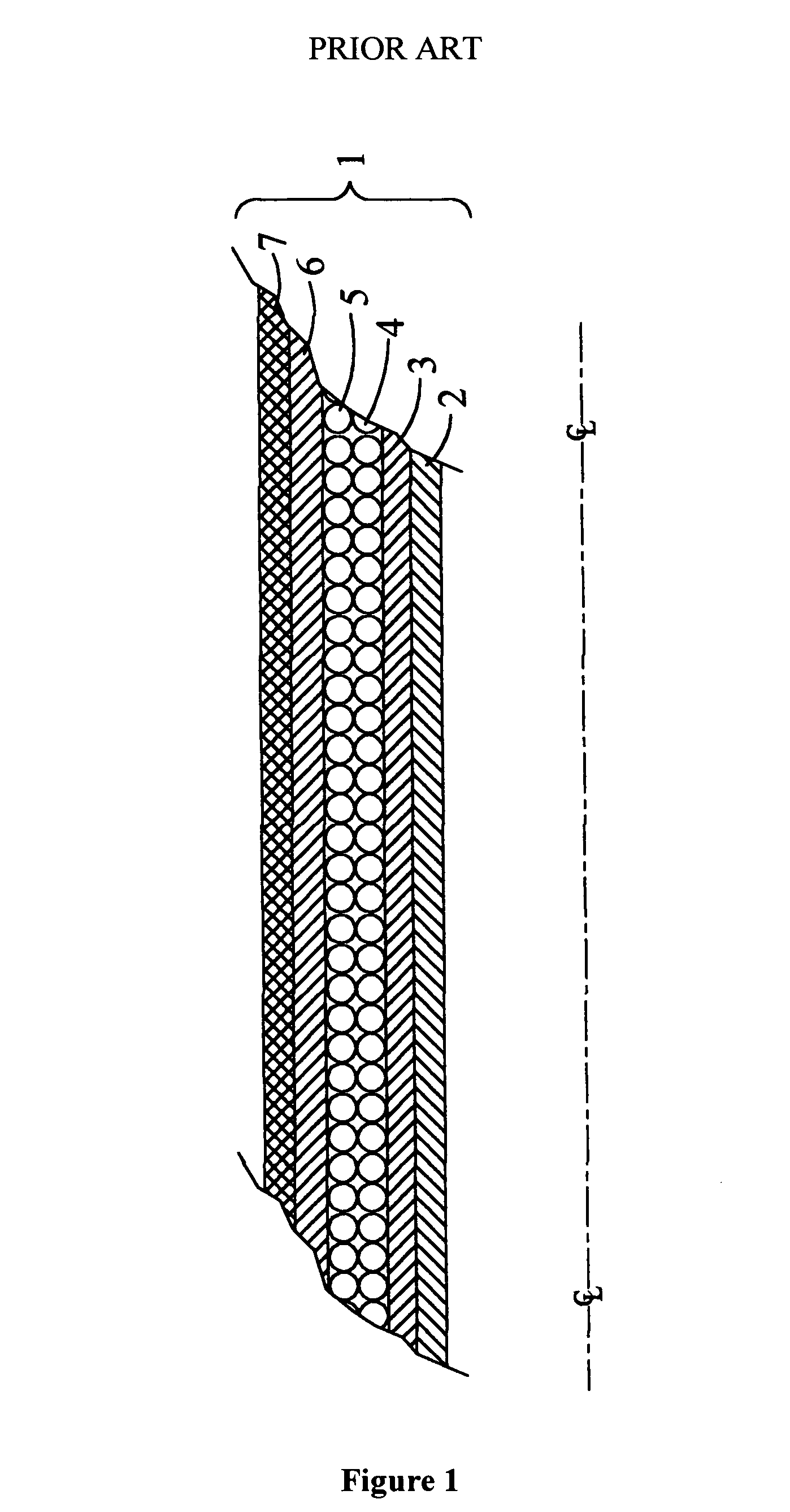
[0058]In order to obtain a high-pressure flexible rubber hose (the term rubber, or elastomer, is used generally and does not specifically mean natural occurring rubber gum), a hose manufacturer incorporates a reinforcing material. Referring to FIG. 1, the reinforced hose, 1, will typically consist of an inside sealing membrane, 2—the fluid tight element, an inner rubber element, 3, a reinforcing element(s), 4 and 5, an outer rubber element, 6, and finally some sort of abrasive resistant covering, 7. The reinforcing element can be polyester or similar organic material or metal generally in the form of steel wire or cable.

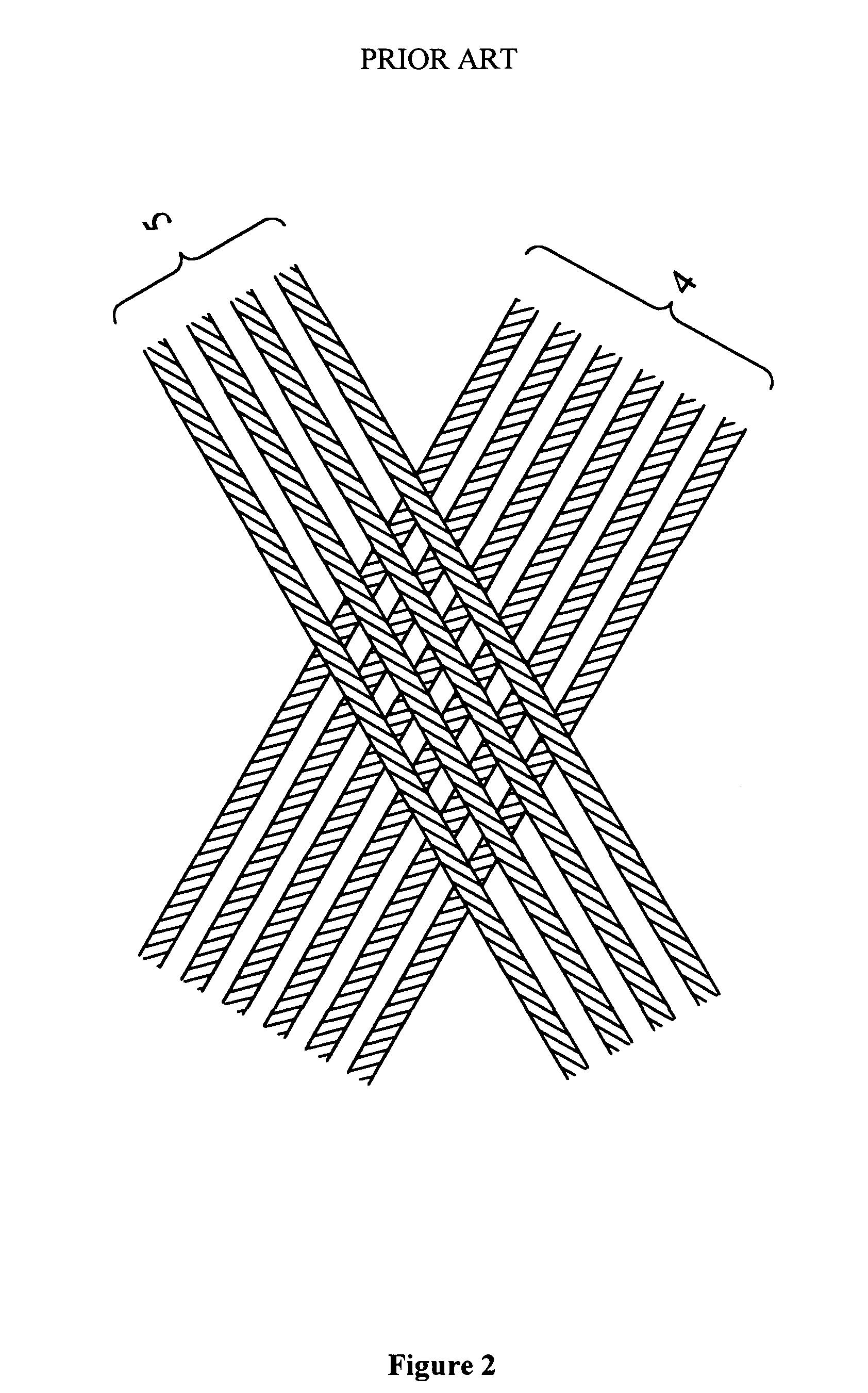
[0059]As can be seen in FIG. 2 the layers of reinforcement are formed at an angle to each other. ...


PUM

PropertyMeasurementUnit
angles DELTAaaaaaaaaaa
burst pressureaaaaaaaaaa

Abstract

Swage end-connector for high pressure reinforced flexible hose particularly suitable in the petrochemical and drilling industries for hoses. Two connectors are disclosed one for intermediate hose pressure burst ratings up to 12,500 psi and internal diameters up to 3½ inches and higher hose pressure burst ratings up to 18,750 psi and internal diameters up to 4 inches. Both embodiment connectors will withstand the rated burst pressure of the hose to which they are connected and will withstand a pump-off force that exceeds the burst pressure of the hose. That is, the hose will fail before the connector pops off the hose.

Description

[0001]This application claims the benefit of U.S. Provisional Application No. 60 / 377,393, filed on May 3, 2002.TECHNICAL FIELD OF THE INVENTION[0002]The present invention relates generally to the reinforced rubber hose industry and in particular to swaged or crimped hose couplings used to terminate high pressure flexible reinforced rubber hose used particularly in the energy, marine, petrochemical industry and other industries.BACKGROUND OF THE INVENTION[0003]High-pressure rubber hose is used in many instances in industry but particularly in the mining, construction, energy, marine and petrochemical industries. Flexible rubber hose is used to transfer fluids under various pressures and temperature between two points, one or both of which, may move relative to each other or to another fixed point in space. Piping at the two points is generally metal (or some other form of fixed conduit) and the flexible hose must attach to the piping at both ends. This requires a coupling on each end...

Claims


Application Information

Patent Timeline
Patent Type & Authority Patents(United States)
IPC IPC(8): F16L33/00F16L33/207
CPCF16L33/01F16L33/2073
Inventor BALDWIN, GARDNER T.DELEON, VICTOR J.SWEENEY, LARRY M.
Owner BALDWIN & LOKE
Why Eureka
Try Eureka