
A steel pipe welding machine that is convenient to drag and straighten

A technology for welding machines and welding racks, applied in welding equipment, auxiliary welding equipment, welding/cutting auxiliary equipment, etc., can solve the problems of increased cost and poor connection, and achieve increased speed, improved work efficiency, and increased transportation speed effect

Active Publication Date: 2021-05-11
浙江锦霖运动科技有限公司
View PDF10 Cites 0 Cited by
  • Summary
  • Abstract
  • Description
  • Claims
  • Application Information

AI Technical Summary

Problems solved by technology

[0002] As one of the most important methods of combining mechanical structures, welding technology has been widely used in production and life. With the development of science and technology and social progress, steel pipes are used more and more widely, and the demand is increasing. Thin Wall steel pipe is also a kind of steel pipe. The forming of steel pipe is generally by casting or stamping, but the length of steel pipe is limited by casting or stamping. Therefore, in practical application, it is often necessary to butt the steel pipe. Socketing and welding are mostly used for welding. Welding is divided into manual welding and mechanical girth welding. Most of the production lines with large output use mechanical girth welding. Casting and mechanical girth welding are used to process thin-walled steel pipes. There is a certain deformation of the steel pipe after use, which makes the butt connection impossible during welding, and different types of steel pipes require different welding machines for welding, resulting in increased costs

Method used


Image

  • A steel pipe welding machine that is convenient to drag and straighten
  • A steel pipe welding machine that is convenient to drag and straighten
  • A steel pipe welding machine that is convenient to drag and straighten

Examples


Embodiment

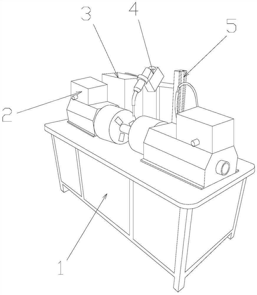
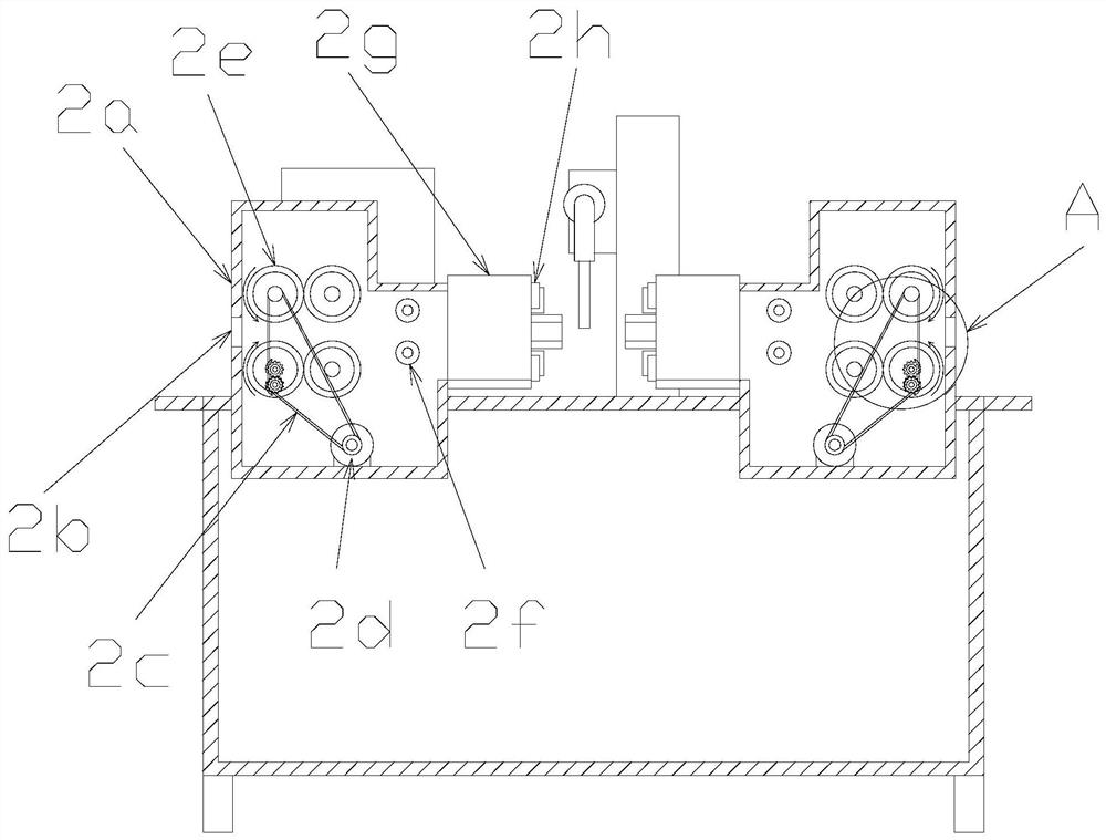
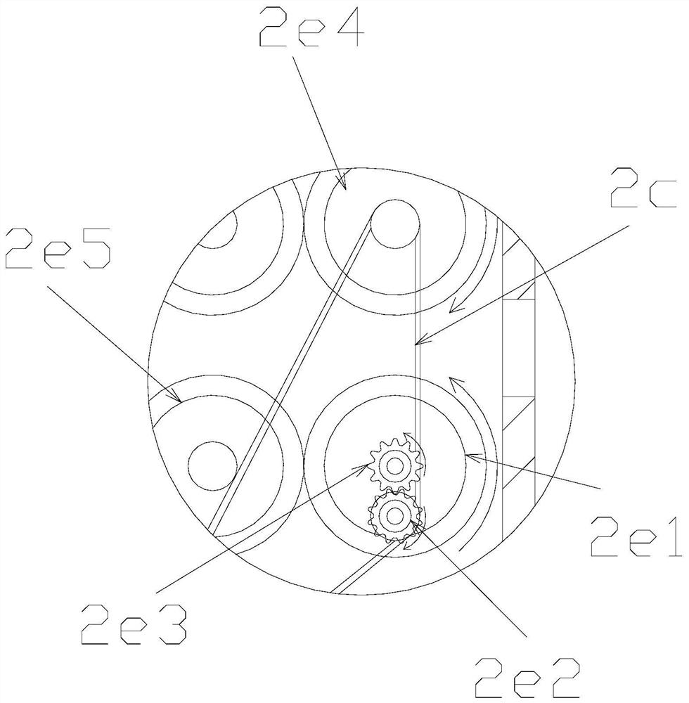
[0031] see Figure 1-Figure 8 , the present invention provides a steel pipe welding machine that is convenient to drag and straighten. Its structure includes a welding frame 1, a dragging device 2, a power distribution control cabinet 3, a welder 4, and a welding rail frame 5. The welding frame Two dragging devices 2 are installed on the top of 1, and a welding guide rail frame 5 is arranged between the two dragging devices 2, and the welding rail frame 5 is movably connected with the welding frame 1, and the welding guide rail A welder 4 is provided on the surface of the frame 5, and the welding rail frame 5 and the welder 4 are slidably matched. The power distribution control cabinet 3 is installed on the surface of the welding frame 1, and the dragging device 2 is controlled by the machine body. 2a, feeding hole 2b, transmission belt 2c, driving motor 2d, feeding mechanism 2e, positioning guide wheel 2f, steel pipe fixing head 2g, and chuck mechanism 2h. The body 2a is prov...


PUM


Abstract

The invention discloses a steel pipe welding machine which is convenient to drag and straighten. Its structure includes a welding frame, a drag device, a power distribution control cabinet, a welder, and a welding rail frame. The drag device uses a driving motor to drive and feed materials through a transmission belt. When the mechanism works, the driving gear drives the first active drag wheel to rotate through the driven gear, so that the first active drag wheel and the second active drag wheel rotate in the opposite direction, increasing the speed of dragging the steel pipe into the drag device, and the first active drag wheel The drag wheel is driven by the internal meshing with the driven pressure wheel, and the driven pressure wheel adjusts the deformed steel pipe through the arc-shaped pressure plate, so as to avoid the two steel pipes from being out of joint during welding, resulting in welding errors. The rod controls the position of the arc-shaped pressure plate and increases the inner diameter range of the main body of the driven pressure wheel, which is used for welding different types of steel pipes and improves work efficiency.

Description

technical field [0001] The invention relates to the field of steel pipe processing equipment, in particular to a steel pipe welding machine which is convenient to drag and straighten. Background technique [0002] As one of the most important methods of combining mechanical structures, welding technology has been widely used in production and life. With the development of science and technology and social progress, steel pipes are used more and more widely, and the demand is increasing. Thin Wall steel pipe is also a kind of steel pipe. The forming of steel pipe is generally by casting or stamping, but the length of steel pipe is limited by casting or stamping. Therefore, in practical application, it is often necessary to butt the steel pipe. Socketing and welding are mostly used for welding. Welding is divided into manual welding and mechanical girth welding. Most of the production lines with large output use mechanical girth welding. Casting and mechanical girth welding ar...

Claims


Application Information

Patent Timeline
Patent Type & Authority Patents(China)
IPC IPC(8): B23K37/053B23K37/047
CPCB23K37/047B23K37/053B23K37/0533
Inventor 王秋平
Owner 浙江锦霖运动科技有限公司
Learn More