Crank retractor handle

Active Publication Date: 2008-03-04
THOMPSON SURGICAL INSTR
View PDF24 Cites 22 Cited by
  • Summary
  • Abstract
  • Description
  • Claims
  • Application Information

AI Technical Summary

Benefits of technology

[0012]The apparatus includes an adapter housing having a retractor handle passageway, the retractor handle passageway being configured to both receive the slideable insertion of the non-cylindrical retractor blade handle, and to prevent the rotation of the non-cylindrical retractor blade handle relative to the adaptor housing. At least a portion of the adaptor housing is configured for rotatable insertion into the clamping bore of the universal joint, thereby permitting the rotation of both the adaptor housing and non-cylindrical retractor blade handle, and attached retractor blade, about the longitudinal axis of the non-cylindrical retractor blade handle.
[0013]In one embodiment, a pinion is operably connected to the adapter housing. The pinion is configured for engagement with at least one of a plurality of serrations on the non-cylindrical retractor blade handle, thereby aiding in the linear positioning of the non-cylindrical retractor blade handle. A pawl mechanism is operably connected to the adaptor housing for engagement

Problems solved by technology

Unfortunately, unlike cylindrical retractor blade handles, the square or rectangular configurations of the retractor blade handle and mating orifice render the retractor blade handle incapable of rotation within

Method used


Image

  • Crank retractor handle
  • Crank retractor handle
  • Crank retractor handle

Examples


Embodiment Construction

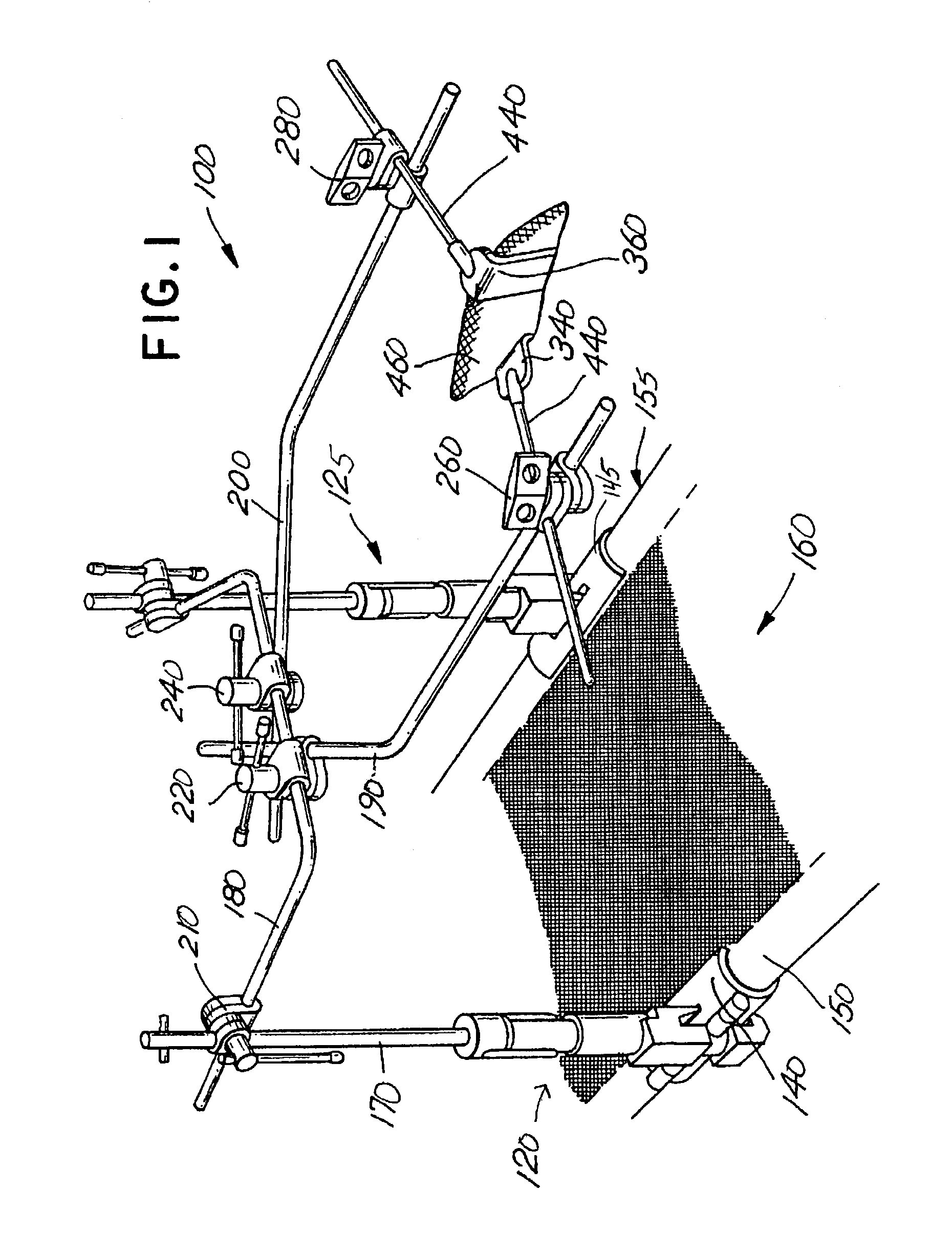
[0024]FIG. 1 illustrates the use of conventional universal joints in a surgical retraction system 100. Adjustable clamps 120, 125 are secured, through the use of adapters 140, 145, to the frames 150, 155 of a conventional framed stretcher or surgical table 160. A post 170 extends vertically from a clamp 120 to provide support for a cross bar 180, which in turn provides support for a pair of extension arms 190, 200. The crossbar 180 is secured to the post 170 by a multidirectional joint clamp 210. The extension arms 190, 200 are secured to the cross bar 180 by a pair of multidirectional joint clamps 220, 240. Additional joint clamps 260, 280 are disposed along the extension arms 190, 200 for rigidly securing any number of retractor blades 340, 360 to the extension arms 190, 200.

[0025]The joint clamps 260, 280 allow for both the rotation of the clamping mechanism along the longitudinal axis of the extension arms 190, 200 and the pivotable placement of the retractor blade handle 440 in...


PUM


Abstract

The present invention relates to an apparatus for adapting a non-cylindrical serrated surgical retractor blade handle to the cylindrical bore of a universal joint. The apparatus includes an adaptor housing having a retractor handle passageway, at least a portion of the retractor handle passageway being configured to receive the slideable insertion of a non-cylindrical retractor blade handle. The adaptor housing is configured for rotational insertion into the cylindrical bore of a clamping member, thereby allowing the adaptor housing, the non-cylindrical retractor blade handle, and an attached retractor blade, to rotate about the longitudinal axis of the non-cylindrical retractor blade handle. In the illustrated embodiment, a pawl mechanism is connected to the adaptor housing and configured for automatic engagement with at least one of a plurality of serrations that are located on the non-cylindrical retractor blade handle, thereby allowing for the efficient adjustment and automatic locking of the linear position of the non-cylindrical retractor blade handle relative to the operative site.

Description

BACKGROUND OF THE INVENTION[0001]The present invention pertains to surgical retractor systems. More particularly, the present invention relates to an apparatus for adapting a non-cylindrical serrated surgical retractor blade handle to a universal joint, and, more particularly, an adaptor that provides the ability to rotate a non-cylindrical retractor blade handle within a universal joint clamping apparatus. The present invention provides surgeons with the ability to precisely position retractor blades, while also providing a ratchet engagement for efficient adjustment and automatic locking of the linear position of a non-cylindrical retractor blade handle and associated retractor blade.[0002]In surgical operations, it is customary to use a retraction device in order to properly access internal organs and bone structures. Such devices are particularly designed to hold back a patient's anatomy in the immediate area of the operative site, thereby enabling a surgeon to have both an opti...

Claims


Application Information

Patent Timeline
IPC IPC(8): A61B1/32A61B17/02A61B19/00
CPCA61B17/02A61B17/0206A61B19/26A61B90/50
Inventor MULAC, ANTHONY J.FARLEY, DANIEL K.
Owner THOMPSON SURGICAL INSTR
Why Eureka
Try Eureka