Centrifugal separator for cleaning gas generated by an internal combustion engine and a method for operating the same

a technology of centrifugal separator and internal combustion engine, which is applied in the direction of centrifuges, separation processes, auxillary pretreatment, etc., can solve the problems of contaminating the cleaned gas, defeating destroying the purpose of centrifugal separator, so as to achieve the effect of minimizing the potential for oil egress

Active Publication Date: 2008-03-04
ALFA LAVAL CORP AB
View PDF40 Cites 67 Cited by
  • Summary
  • Abstract
  • Description
  • Claims
  • Application Information

AI Technical Summary

Benefits of technology

[0009]The present invention resides in one aspect in a centrifugal separator for cleaning gases generated by an internal combustion engine. The separator includes a housing defining an interior separation chamber. A centrifugal rotor is rotatably coupled to the housing and extends into the separation chamber. Driving means are also provided and upon operation cause centrifugal rotor to spin. A drainage chamber is positioned adjacent the separation chamber and is delimited therefrom by a partition wall. Means are provided that define a flow path through which oil, separated from gas generated by the internal combustion engine can travel via gravity from the separation chamber to the drainage chamber. These means also allow for pressure to be equalized in the separation and drainage chambers. A pump wheel is coupled to a shaft portion of the rotor and extends radially outwardly therefrom. During operation the oil, upon exiting the separation chamber, contacts the pump wheel whereby centrifugal forces generated due to the rotation of the pump wheel cause the oil to be thrown into the drainage chamber. The pump wheel performs a pumping action when moving oil that contacts the disc from a smaller diameter to a larger diameter, which minimizes the potential for oil resident in the drainage chamber from being able to re-enter the separation chamber.
[0012]In still another embodiment of the present invention, the pump wheel defines an annular groove extending part-way through the pump wheel and circumferentially there around. The partition wall includes a downwardly depending portion defining a bore adapted to receive the outer race of a bearing that rotatably supports the centrifugal rotor. The downwardly depending portion further defines a lip at a lower end thereof that extends at least partially over an end face defined by the outer race of the bearing. The lip acts to retain the bearing in a predefined position. The lower end of the downwardly extending portion extends into the groove defined by the pump wheel and cooperates therewith to define a drainage pump. Accordingly, during operation of the centrifugal separator, oil separated from gas generated by the internal combustion engine, flows through the bearing and onto the pump wheel. The rotation of the pump wheel causes the oil to flow from a smaller to a larger diameter of the pump wheel. In so doing, the oil passes through the drainage pump and is then thrown into the drainage chamber. The drainage pump also minimizes the potential for oil to flow from the drainage chamber to the separating chamber. Moreover, while providing a sealing function, the drainage pump also allows for pressure equalization between the separation and sealing chambers.
[0013]In yet another embodiment of the present invention, the means defining a flow path includes at least one aperture positioned near the outer race of the bearing and above the pump wheel. During operation, oil separated from the gas generated by the combustion engine flows through the aperture, into the drainage chamber and onto the separation disc. The rotation of the separation disc causes the oil to be thrown from an edge thereof, into the drainage chamber. The at least one aperture can also include a plurality of apertures extending circumferentially around the outer race of the bearing to provide a larger number of holes through which separated oil can drain.
[0016]Upon operation of the internal combustion engine, the drive means causes the rotor of the centrifugal separator to spin. Gas generated by the internal combustion engine enters the separation chamber and includes entrained material such as oil therein. The centrifugal separator operates to separate the entrained material from the gas so that the oil (which forms part of the entrained material) collects in the separation chamber and flows to an inner surface defined by the partition wall where, via gravity and the means defining a flow path, the oil drains from the separation chamber into the drainage chamber and into contact with the pump wheel. The rotation of the pump wheel imparts centrifugal force to the oil thereby causing the oil to be thrown from the pump wheel into the drainage chamber. The rotation of the pump wheel also minimizes the potential for the egress of oil from the drainage chamber into the separation chamber due to the tendency of oil contacting the pump wheel to be thrown, via centrifugal force generated thereby, back into the drainage chamber.

Problems solved by technology

A difficulty that occurs with the above-described centrifugal separator is that because these devices are used in connection with internal combustion engines, it is possible for the centrifuge to assume different orientations whether due to mounting constraints or, if used in a vehicle, the different attitudes a vehicle may assume during driving.
Depending on the degree of incline of the centrifugal separator, there is a potential for separated material such as oil to leak into the cleaned gas and be discharged from the clean gas outlet, thereby defeating the purpose of the centrifugal separator.
Another potential problem associated with centrifugal separators configured as described above is that the operation of the turbine and the driving oil being forced there against can cause the driving oil to leak into the separation chamber through the bore 34 and contaminate the cleaned gas, again defeating the purpose of the centrifugal separator.

Method used


Image

  • Centrifugal separator for cleaning gas generated by an internal combustion engine and a method for operating the same
  • Centrifugal separator for cleaning gas generated by an internal combustion engine and a method for operating the same
  • Centrifugal separator for cleaning gas generated by an internal combustion engine and a method for operating the same

Examples


Embodiment Construction

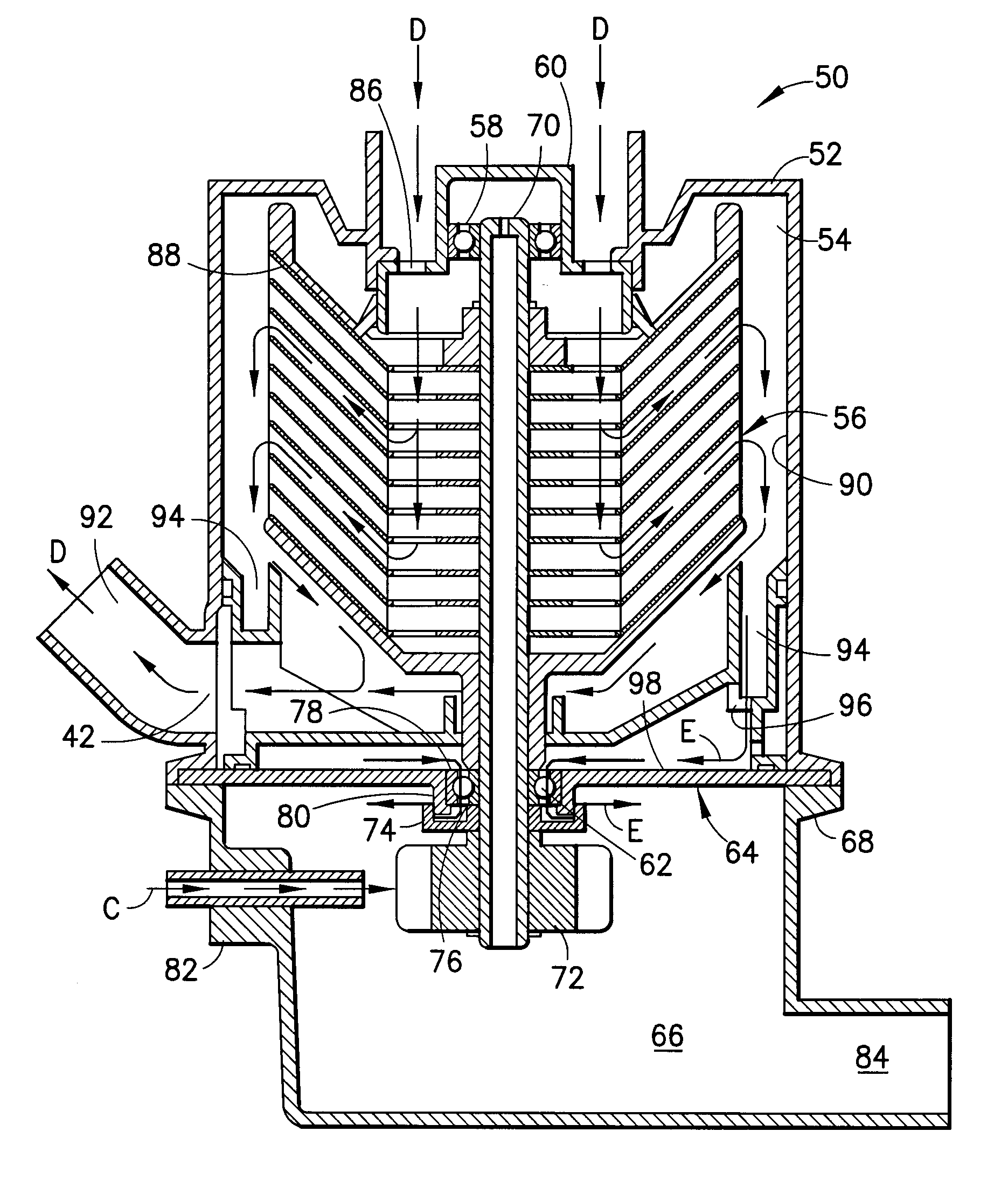
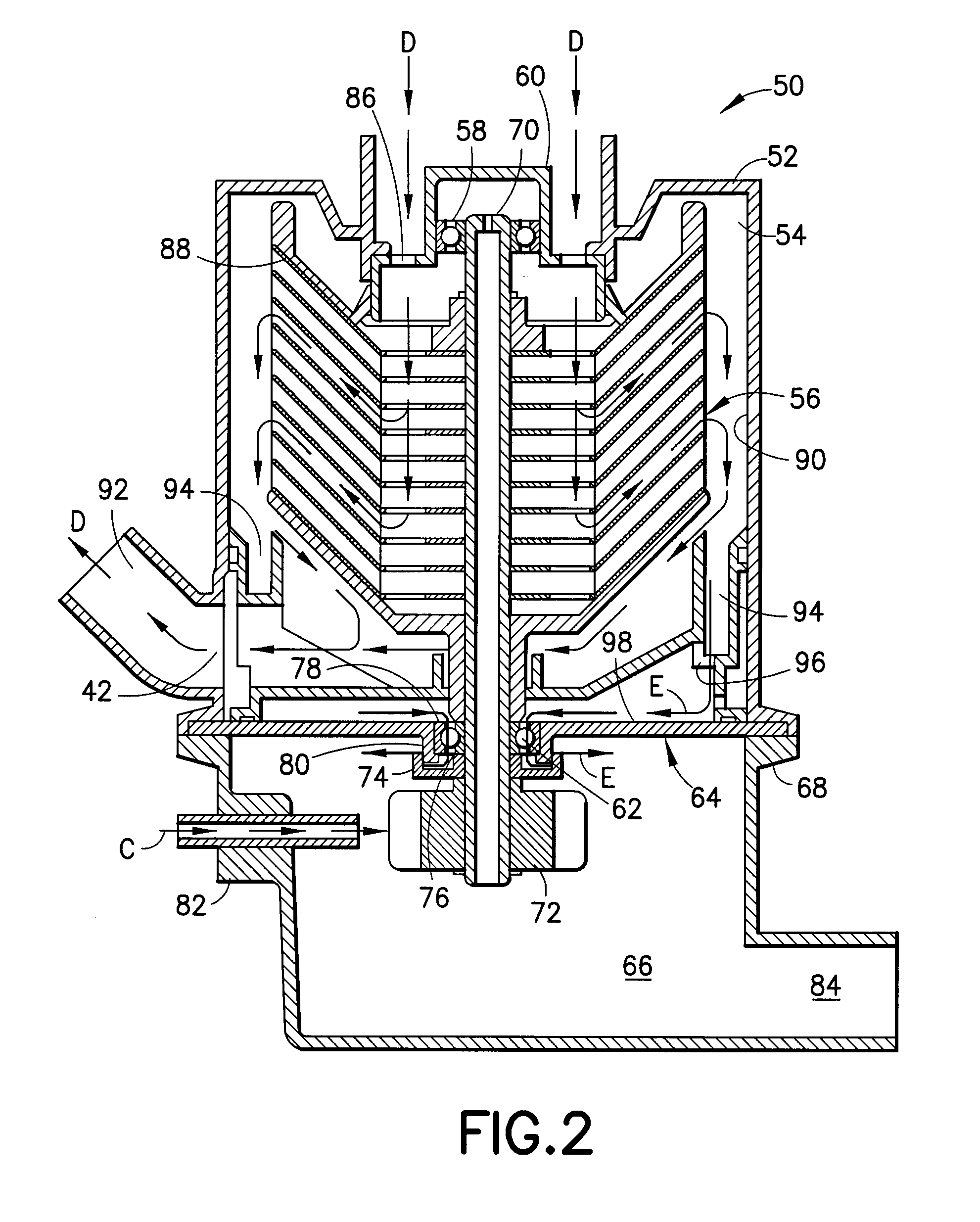
[0024]As shown in FIG. 2 a centrifugal separator generally designated by the reference number 50 includes a stationary housing 52 that defines an interior separation chamber 54. A centrifugal rotor generally designated by the reference number 56 is rotatably positioned in the separation chamber 54. An upper bearing, 58 is mounted to a bearing housing 60, which in turn is attached to the stationary housing 52. A lower bearing 62 is mounted to a partition wall 64 which delimits the separation chamber 54 from an interior drainage chamber 66 defined by a drainage housing 68. The drainage housing 68 is in turn coupled to the stationary housing 52 at a lower end thereof. A drive shaft 70 forming part of the centrifugal rotor 56 is supported for rotation in the upper and lower bearings, 58 and 62 respectively. A portion of the drive shaft 70 extends through the lower bearing 62 and into the drainage chamber 66.

[0025]A turbine 72 is positioned in the drainage chamber 66 and is mounted for r...


PUM

PropertyMeasurementUnit
pressureaaaaaaaaaa
centrifugal forcesaaaaaaaaaa
gravityaaaaaaaaaa

Abstract

In a centrifugal separator for cleaning gases generated by an internal combustion engine a housing defines an interior separation chamber. A centrifugal rotor is coupled for rotation to the housing and extends into the separation chamber. A drainage chamber is positioned adjacent the separation chamber and is delimited therefrom by a partition wall. A flow path is provided through which oil, separated from gases generated by the internal combustion engine and collecting on the partition wall, can travel from the separation chamber to the drainage chamber. A pump wheel is coupled to a shaft portion defined by the rotor and extends radially outwardly therefrom. During operation the oil, upon exiting the separation chamber, contacts the pump wheel. Centrifugal forces generated due to the rotation of the pump wheel cause the oil to be thrown into the drainage chamber. The pump wheel also minimizes the potential for oil resident in the drainage chamber to re-enter the separation chamber.

Description

FIELD OF THE INVENTION[0001]The present invention is directed to a centrifugal separator useful in the separation of entrained material, including oil, from gases generated by an internal combustion engine whereby the oil is drained from a separation chamber into a drainage chamber.BACKGROUND OF THE INVENTION[0002]Centrifugal separators useful in separating entrained material, including oil, from gases generated by an internal combustion engine are sometimes configured so that a housing defines a separation chamber into which a centrifuge rotor is positioned. The rotor is typically mounted for rotation in bearings supported by the housing and is driven by a suitable drive coupled to a shaft portion of the rotor that extends through one of the bearings and out of the separation chamber. During operation, oil separated from the gas must be drained from the separation chamber.[0003]A typical centrifugal separator useful for cleaning gas generated by an internal combustion engine, such ...

Claims


Application Information

Patent Timeline
Patent Type & Authority Patents(United States)
IPC IPC(8): B01D45/00
CPCB01D45/14B04B5/005B04B5/12B04B9/06B04B9/12F01M13/04B04B2005/125F01M2013/0422
Inventor ELIASSON, THOMASSZEPESSY, STEFAN
Owner ALFA LAVAL CORP AB
Why Eureka
Try Eureka